M74HC356 데이터 시트보기 (PDF) - STMicroelectronics
부품명
상세내역
일치하는 목록
M74HC356 Datasheet PDF : 12 Pages
| |||
M54/M74HC356
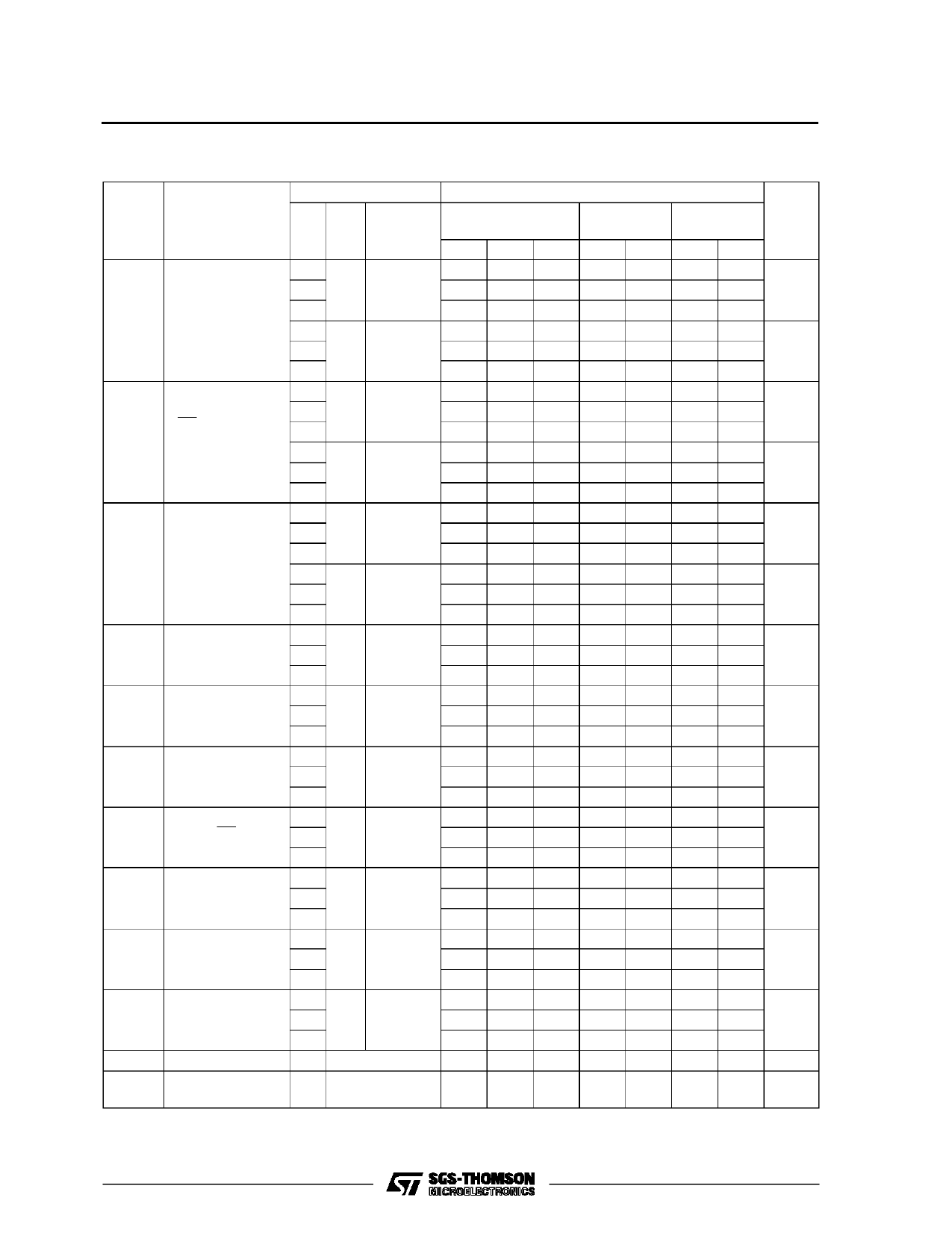
AC ELECTRICAL CHARACTERISTICS (CL = 50 pF, Input tr = tf = 6 ns)
Symbol
Parameter
Test Conditions
VCC CL
(V) (pF)
TA = 25 oC
54HC and 74HC
Value
-40 to 85 oC -55 to 125 oC Unit
74HC
54HC
Min. Typ. Max. Min. Max. Min. Max.
tPLH Propagation
tPHL Delay Time
(Sn - Y, W)
2.0
4.5 50
6.0
111 260
325
390
32 52
65
78
ns
24 44
55
66
2.0
4.5 150
128 300
375
450
37 60
75
90
ns
6.0
28 51
64
77
tPLH Propagation
tPHL Delay Time
(SC - Y, W)
2.0
4.5 50
6.0
115 270
340
405
33 54
68
81
ns
25 46
58
69
2.0
4.5 150
132 310
390
465
38 62
78
93
ns
6.0
29 53
66
79
tPZL 3 State Output
2.0
48 125
155
190
tPZH Enable Time
4.5 50 RL = 1 KΩ
14 25
31
38
ns
6.0
11 21
26
32
2.0
65 165
205
250
4.5 150 RL = 1 KΩ
19 33
41
50
ns
6.0
15 28
35
43
tPLZ 3 State Output
2.0
43 155
195
235
tPHZ Disable Time
4.5 50 RL = 1 KΩ
18 31
39
47
ns
6.0
16 26
33
40
fMAX Maximum Clock 2.0
Frequency
4.5 50
6.2 20
5
4.2
31 80
25
21
ns
6.0
37 82
30
25
tW(L)
tW(H)
Minimum Pulse
Width (CLOCK)
2.0
4.5 50
25 75
6
15
95
110
19
22
ns
6.0
6
13
16
19
tW(L) Minimum Pulse
Width (SC)
2.0
4.5 50
13 75
6
15
95
110
19
22
ns
6.0
6
13
16
19
ts
Minimum Set-up 2.0
Time (Dn)
4.5 50
21 50
65
75
4
10
113
15
ns
6.0
3
9
11
13
ts
Minimum Set-up 2.0
Time (Sn)
4.5 50
9
50
65
75
2
10
13
15
ns
6.0
2
9
11
13
th
Minimum Hold
2.0
Time (Dn) (Sn)
4.5 50
5
5
5
5
5
5
ns
6.0
5
5
5
CIN Input Capacitance
5
10
10
10
pF
CPD (*) Power Dissipation
59
Capacitance
pF
(*) CPD is defined as the value of the IC’s internal equivalent capacitance which is calculated from the operating current consumption without load.
(Refer to Test Circuit). Average operting current can be obtained by the following equation. ICC(opr) = CPD •VCC •fIN + ICC
6/12
Share Link: 