NTE7129 데이터 시트보기 (PDF) - NTE Electronics
부품명
상세내역
일치하는 목록
NTE7129
NTE Electronics

NTE7129 Datasheet PDF : 4 Pages
| |||
Absolute Maximum Ratings: (TA = +25°C unless otherwise specified)
Maximum Supply Voltage, VCCmax . . . . . . . . . . . . . . . . . . . . . . . . . . . . . . . . . . . . . . . . . . . . . . . . . 13.8V
Allowable Power Dissipation (TA ≤ +50°C), Pdmax . . . . . . . . . . . . . . . . . . . . . . . . . . . . . . . . . 1200mW
Circuit Voltage, V3, V13 . . . . . . . . . . . . . . . . . . . . . . . . . . . . . . . . . . . . . . . . . . . . . . . . . . . . . . . . . . . . . . VCC
Circuit Voltage, V14 . . . . . . . . . . . . . . . . . . . . . . . . . . . . . . . . . . . . . . . . . . . . . . . . . . . . . . . . . . . . . . . . . VCC
Circuit Current, I1 . . . . . . . . . . . . . . . . . . . . . . . . . . . . . . . . . . . . . . . . . . . . . . . . . . . . . . . . . . . . . . . . . −1mA
Circuit Current, I17 . . . . . . . . . . . . . . . . . . . . . . . . . . . . . . . . . . . . . . . . . . . . . . . . . . . . . . . . . . . . . . . −10mA
Circuit Current, I21 . . . . . . . . . . . . . . . . . . . . . . . . . . . . . . . . . . . . . . . . . . . . . . . . . . . . . . . . . . . . . . . . −3mA
Circuit Current, I10 . . . . . . . . . . . . . . . . . . . . . . . . . . . . . . . . . . . . . . . . . . . . . . . . . . . . . . . . . . . . . . . . . 3mA
Operating Temperature Range (Note 2), Topr . . . . . . . . . . . . . . . . . . . . . . . . . . . . . . . . . . −20° to +70°C
Storage Temperature Range, Tstg . . . . . . . . . . . . . . . . . . . . . . . . . . . . . . . . . . . . . . . . . . −55° to +150°C
Note 1. The current that flows into the IC is positive (no signal); the current that flows out of the IC
is negative.
Note 2. Topr = −20° to +75°C at VCC = 9V.
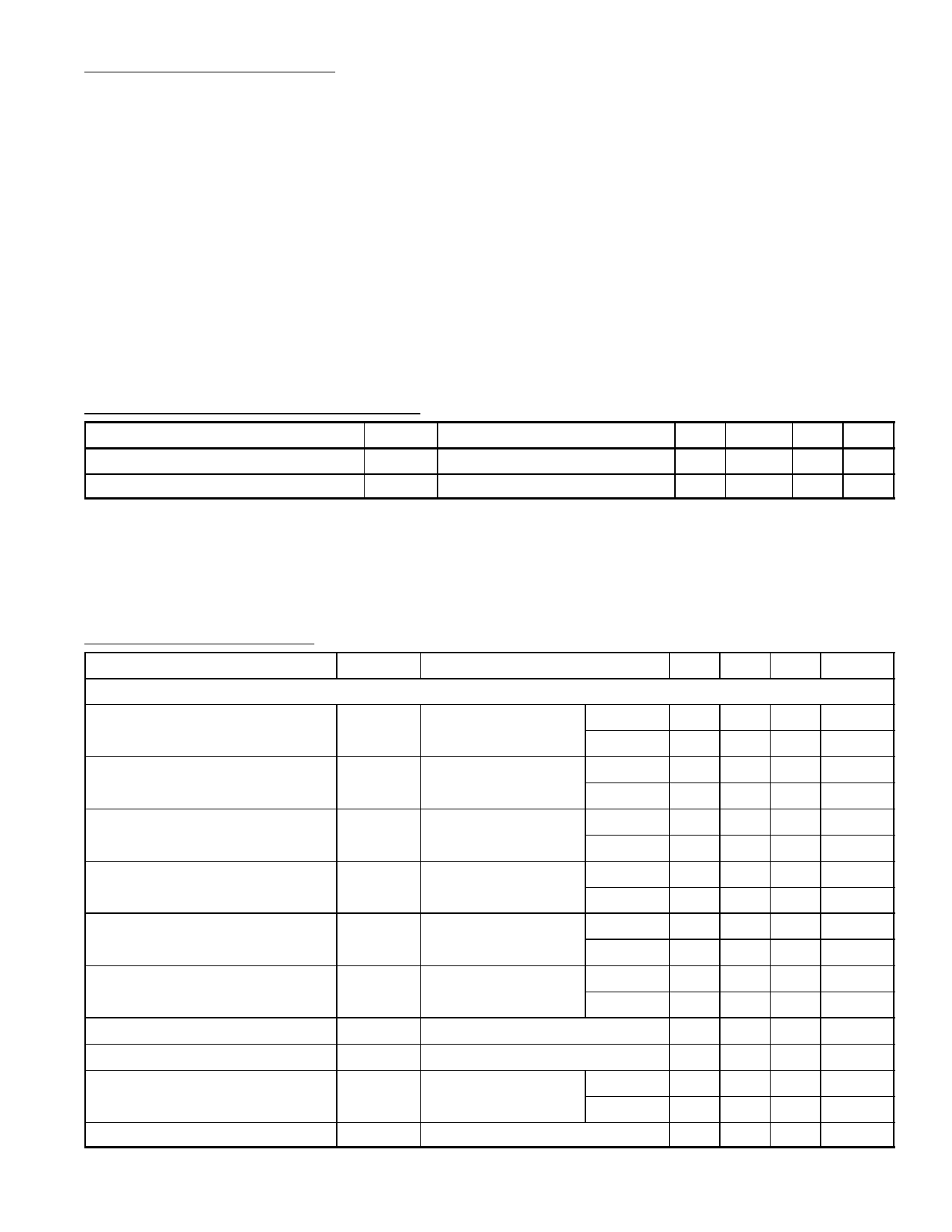
Recommended Operating Conditions: (TA = +25°C unless otherwise specified)
Parameter
Symbol
Test Conditions
Min Typ Max Unit
Recommended Supply Voltage
VCC
9 or 12
V
Operating Supply Voltage Range VCCop
8.2 − 13.2 V
Note 3. Always turn on the protective resistance when drawing a line directly out from the IC at
usage. (Pin2, Pin11, Pin12, etc.)
Note 4. A capacitor with favorable humidity characteristics should be used for Pin13. (ex. OS capacitor)
Note 5. Pin8 (N.C.) should always be open.
Electrical Characteristics: (TA = +25°C, VCC = 12V unless otherwise specified)
Parameter
Symbol
Test Conditions
Min Typ Max
VIF Block
Circuit Current
No−Signal Video Output Voltage
Maximum RF AGC Voltage
I9
V21
V10H
V13 = 5V, S1 = ON
42 48 57
VCC = 9V 36 41 49
V13 = 5V, S1 = ON
6.6 7.0 7.4
VCC = 9V 5.0 5.4 5.8
V13 = 7V, S1 = OFF
10.6 11.0 11.4
Minimum RF AGC Voltage
No−Signal AFT Voltage
Input Sensitivity
AGC Range
VCC = 9V 7.6 8.0 8.4
V10L V13 = 7V, S1 = ON
− 0 0.5
VCC = 9V −
0 0.5
V14 V13 = 5V, S1 = ON
3.0 5.9 8.0
VCC = 9V 2.6 4.5 6.0
Vi
S1 = OFF
33 39 45
VCC = 9V 37 43 49
GR S1 = ON
60 66 −
Maximum Allowable Input
Video Output Amplitude
Output S/N
Vimax S1 = ON
VO(video) S1 = ON
S/N S1 = ON
100 105 −
1.95 2.25 2.55
VCC = 9V 1.5 1.75 2.0
49 55 −
Unit
mA
mA
V
V
V
V
V
V
V
V
dB/µV
dB/µV
dB
dB/µV
VP−P
VP−P
dB
Share Link: