NJM2706 데이터 시트보기 (PDF) - Japan Radio Corporation
부품명
상세내역
일치하는 목록
NJM2706 Datasheet PDF : 15 Pages
| |||
NJM2706
1-3. Adjusting the Summing Level for ealaBASS effect to L/R Output Signal
Changing the resistance value connected between the terminal 8 and 9 can modify the Summing Level for the
ealaBASS effect to the L/R Output Signal.
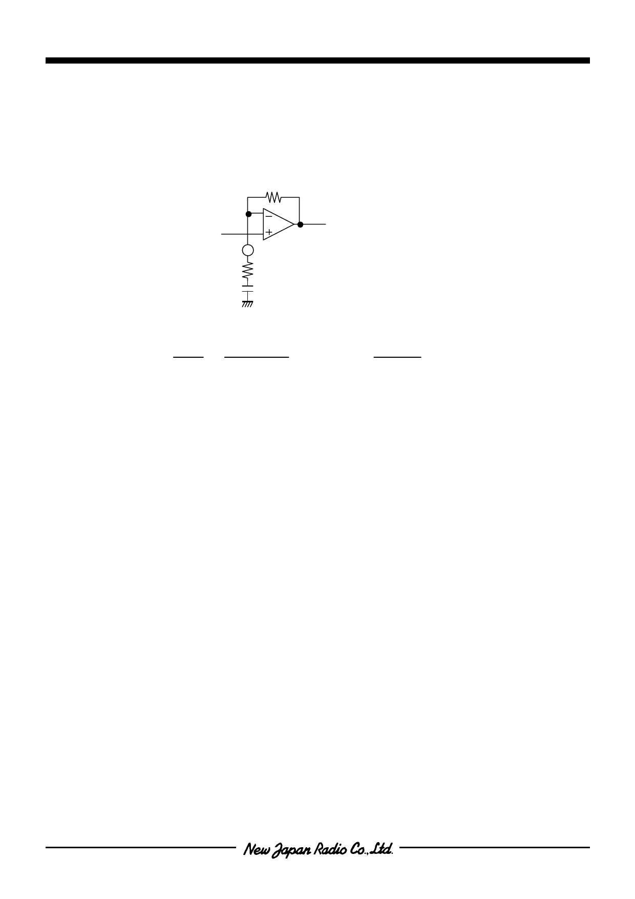
2. Adjusting the High Frequency Compensation Filter
The NJM2706 has High Frequency Compensation Filter, which can produce well balance between boosted–bass
frequency range and treble frequency range. This picture shows the equivalent circuit for the High Frequency
Compensation Filter.
15k
20pi n
HFF IL
R6
30k
C11
560p
* The pin numbers apply in DMP24 and SSOP24's case.
The Cut-off Frequency fCH and the Voltage Gain GVH are defined as below:
fCH=
1
2πCR
=
1
2π×C11×R6
GVH= 20log
R6+15k
R6
In the typical application circuit shown on the page 9, the High Frequency Compensation Filter Cut-off Frequency
fCH is set to 10kHz and Voltage Gain GVH is set to 3.5dB.
- 11 -
Share Link: 