MNA145CN101MK 데이터 시트보기 (PDF) - ROHM Semiconductor
부품명
상세내역
일치하는 목록
MNA145CN101MK Datasheet PDF : 9 Pages
| |||
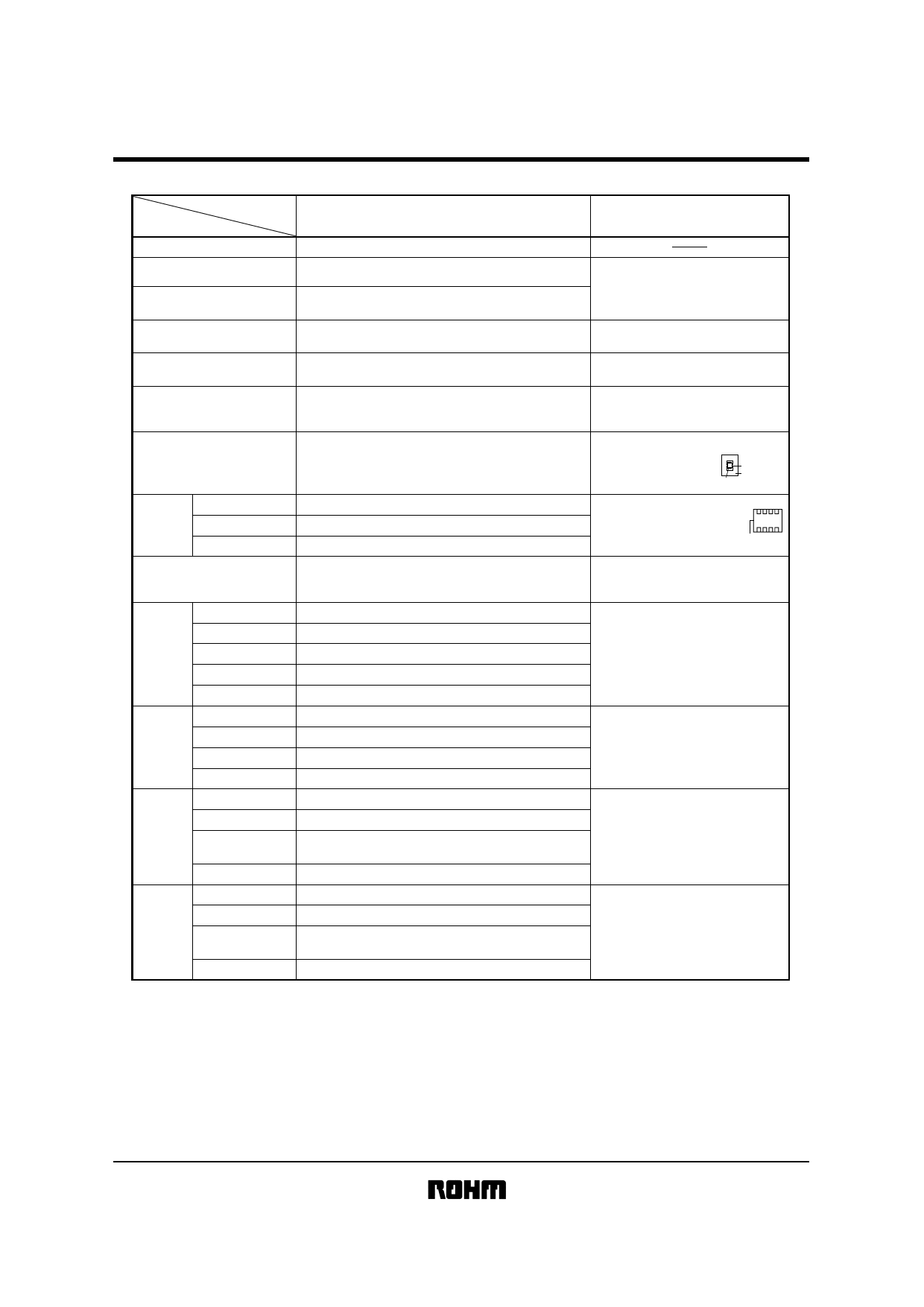
Ceramic capacitors
MNA14
Class 2 (High dielectric constant)
Temperature characteristics
Item
Operating temperature
CN (X7R)
−55°C ~ +125°C
Test methods/conditions
(based on JIS C 5102)
Nominal capacitance (C)
Dissipation factor (tanδ)
Insulation resistance (IR)
Withstanding voltage
Temperature characteristics
Must be within the specified tolerance range.
2.5% or less
(when rated voltage is 16V : 3.5% or less)
10,000MΩ or 500MΩ⋅µF, whichever is smaller
The insulation must not be damaged.
Within ± 15%
Based on paragraph 7.8
Measured at room temperature and standard humidity.
Measurement frequency: 1 ± 0.1 kHz
Measurement voltage : 0.1 ± 0.2 Vrms.
Based on paragraph 7.6
Measurement is made after rated voltage
is applied for 60 ± 5s.
Based on paragraph 7.1
Apply 250% of the rated voltage
for 1 to 5s then measure.
The temperature coefficients in paragraph 7.12,
table 8, condition B, are based on measurements
carried out at 20°C, with no voltage applied.
Terminal adherence
No peeling or sign of peeling on terminal.
Based on paragraph 8.11.2.
Apply 5N for 10 ± 1s
in the direction indicated
by the arrow.
Pressure (5N)
Test board
Capacitor
Resistance
to vibration
Appearance
Rate of capacitance change
Dissipation factor (tanδ)
There must be no mechanical damage.
Must be within initial tolerance.
Must satisfy initial specified value.
Chip is mounted to a board in the
manner shown on the right, subjected
to vibration (type A in paragraph 8.2),
and measured 48 ± 4 hrs. later.
Board
Solderability
At least 3/4 of the surface of the two terminals must be covered with new solder.
Based on paragraph 8.13
Soldering temperature: 235 ± 5°C
Soldering time
: 2 ± 0.5s
Resistance
to soldering
heat
Appearance
Rate of capacitance change
Dissipation factor (tanδ)
Insulation resistance
Withstanding voltage
There must be no mechanical damage.
Within ± 5.0%
Must satisfy initial specified value.
10,000MΩ or 500MΩ⋅µF, whichever is smaller
The insulation must not be damaged.
Based on paragraph 8.14.
Soldering temperature: 260 ± 5°C
Soldering time
Preheating
: 5 ± 0.5s
: 150 ± 10°C for
1 to 2 min.
Appearance
Temperature
cycling
Rate of capacitance change
Dissipation factor (tanδ)
There must be no mechanical damage.
Within ± 7.5%
Must satisfy initial specified value.
Based on paragraph 9.3
Number of cycles : 5
Capacitance measured after 48 ± 4 hrs.
Insulation resistance
10,000MΩ or 500MΩ⋅µF, whichever is smaller
Appearance
Humidity load
test
Rate of capacitance change
Dissipation factor (tanδ)
Insulation resistance
Appearance
High-
temperature
load test
Rate of capacitance change
Dissipation factor (tanδ)
Insulation resistance
There must be no mechanical damage.
Within ± 12.5%
5.0% or less
500MΩ or 25MΩ⋅µF, whichever is smaller
There must be no mechanical damage.
Within ± 10.0%
5.0% or less
1,000MΩ or 50MΩ⋅µF, whichever is smaller
Based on paragraph 9.9
Test temperature : 40 ± 2°C
Relative humidity : 90% to 95%
Applied voltage : rated voltage
Test time
: 500 to 524 hrs.
Capacitance measured after 48 ± 4 hrs.
Based on paragraph 9.10
Test temperature : Max. operating temp.
Applied voltage : rated voltage × 200%
Test time
: 1,000 to 1,048 hrs.
Capacitance measured after 48 ± 4 hrs.
∗The design and specifications are subject to change without prior notice. Before ordering or using, please check the latest technical specification.
Share Link: 