FAN8033 데이터 시트보기 (PDF) - Fairchild Semiconductor
부품명
상세내역
일치하는 목록
FAN8033 Datasheet PDF : 24 Pages
| |||
FAN8033
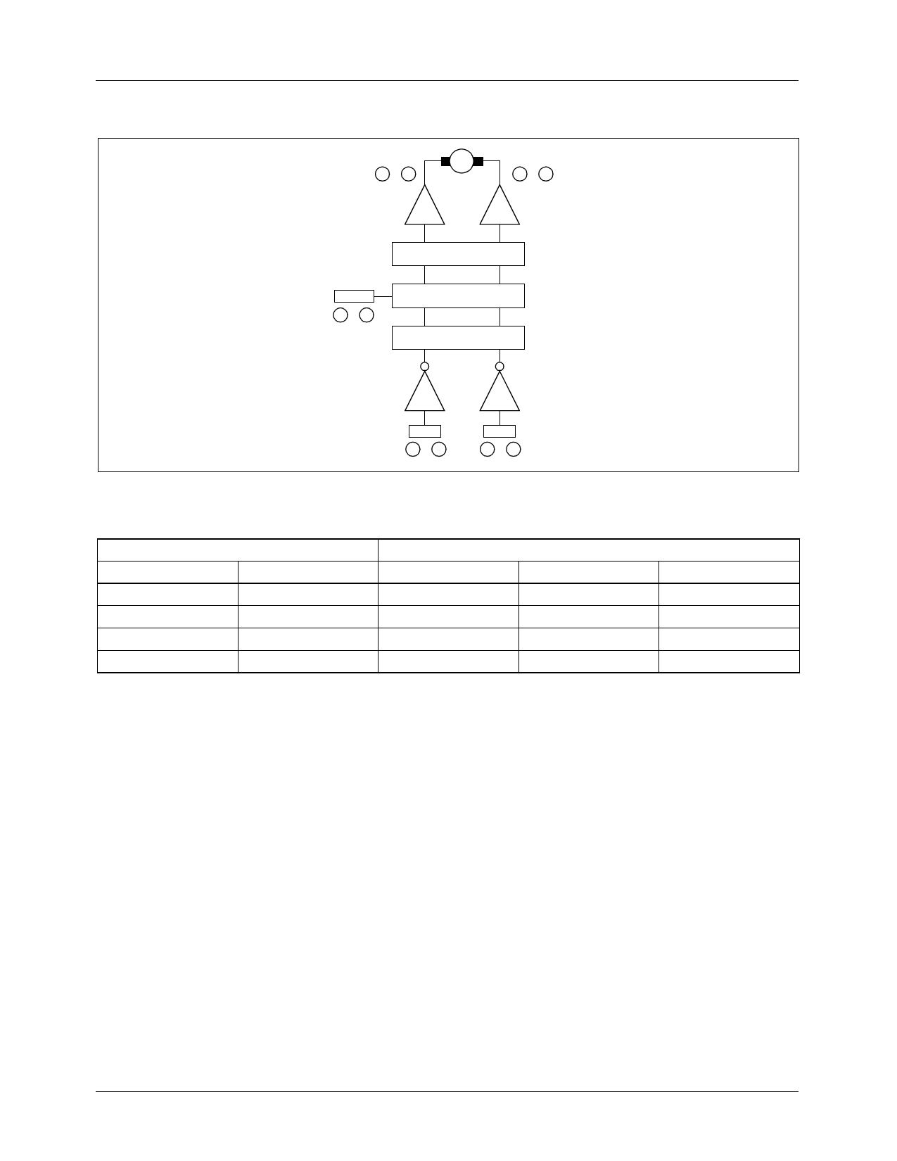
6. TRAY, CHANGE MOTOR DRIVE PART
out 1
M
out 2
24 26
25 27
D
D
CTL1, 2
12 15
LEVEL SHIFT
M.S.C
S.W
IN
FWD
13 16
IN
REV
14 17
• Rotational direction control
The forward and reverse rotational direction is controlled by FWD (pin 13, 16) and REV (pin 14, 17) input conditions are as
follows.
INPUT
OUTPUT
FWD
REV
OUT 1
OUT 2
State
H
H
Vr
Vr
Brake
H
L
H
L
Forward
L
H
L
H
Reverse
L
L
Vr
Vr
Brake
• where Vr is (Vcc - Vbe) / 2 = 3.65V (at Vcc=8V)
• where Out1 pins are pins 24 and 26, and out2 pins aer pins 25 and 27
• Motor speed control
- The almost maximum torque is obtained when it is used with the pins 12 and 15 (CTL1, 2) open.
- If the torque of the motor is too low, then the applied voltage at pins 12 and 15 (CTL1, 2) are 0[V].
- When motor speed controlled, the applied voltage of the pins 12 and 15 (CTL1, 2) is between 0 and 4V.
Also, if the speed control is constant, the applied voltage of the pins 12 and 15 (CTL1, 2) is between 4 and 5V.
- This IC's applied maximum voltage is 6V when VCC is 8V.
- You must not use the applied CTL1, 2 voltage above 5.8V when VCC is 8V, and 3V when VCC is 5V.
16
Share Link: 