MB86616PVF-G-BND 데이터 시트보기 (PDF) - Fujitsu
부품명
상세내역
일치하는 목록
MB86616PVF-G-BND Datasheet PDF : 63 Pages
| |||
MB86616
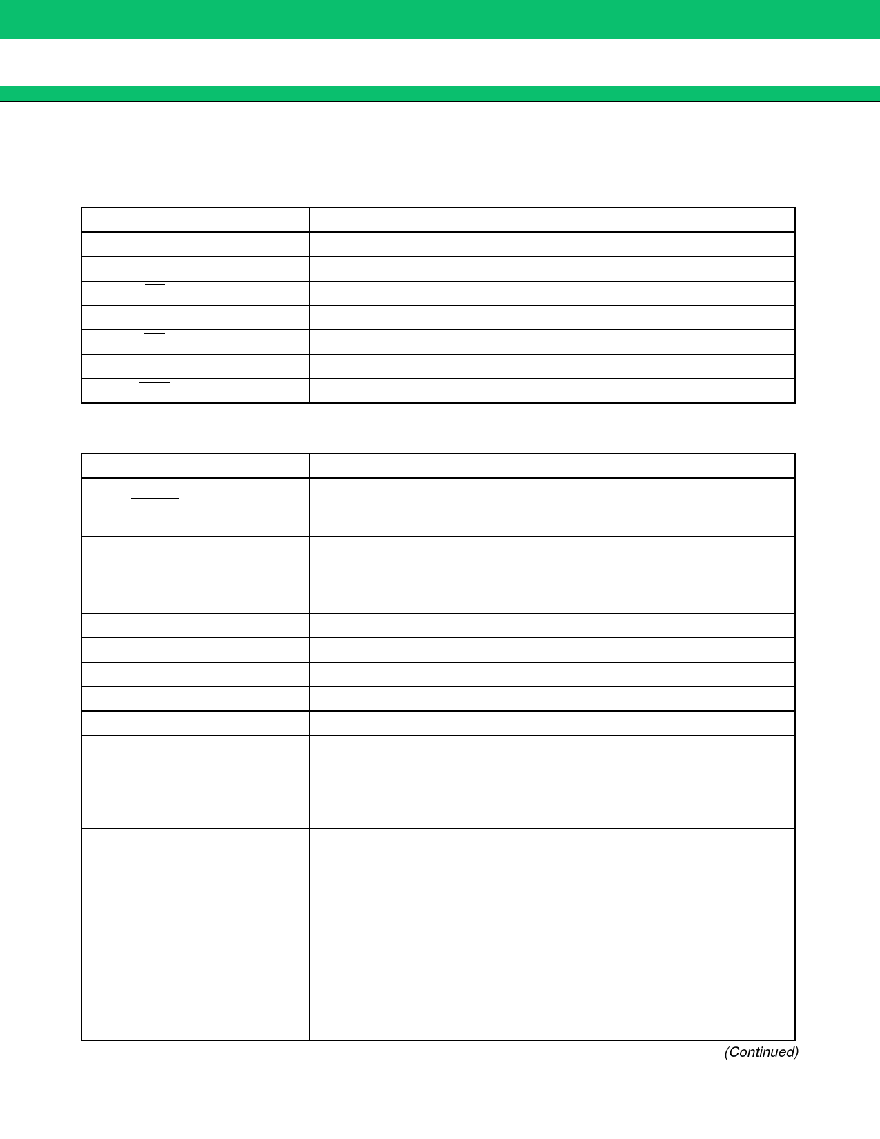
4. CPU Interface (for External CPU Mode)
Note that the pin functions covered in this section are enabled only in the external CPU mode (with the MODEA
pin = “H”) .
Signal name
I/O
Function
A01 to A09
I
External CPU address input pin
D00 to D15
I/O External CPU data input/output pin
CS
I
Pin to input the chip select signal to this device
WR
I
Pin to input the write strobe signal to this device
RD
I
Pin to input the read strobe signal to this device
INT0
O
Interrupt request output pin for the IEEE 1394 block
INT1
O
Interrupt request output pin for the SCSI block
5. Other Pins
Signal name
RESET
MODEA
MODEB, MODEC
SCLK
RF
FIL
R0
CPS
PMODE
PWR1 to PWR3
I/O
Function
Reset signal input pin.
I
Leave this pin at the “L” level while the IEEE 1394 block is operating with
cable supplied power.
Pin for setting the operation mode of this device.
I
“L” input : Use the internal CPU.
“H” input : Use an external CPU to control this device without using the
internal CPU.
I
Connect these pins to GND.
I
Reference clock input pin for the internal PLL (24.576 MHz)
O
Connect this pin to GND via a 5.1 kΩ resistor.
O
External filter circuit connection pin for the internal PLL
O
Connect this pin to GND via a 5.1 kΩ resistor.
Pin to input power supplied through the IEEE 1394 cable.
The pin detects cable supplied power of 0 to 33 V (an external resistor is re-
I
quired to regulate/divide the voltage) .
Connect this pin to GND if the device is not powered through the IEEE 1394
cable.
Power input evaluation pin.
“L” input : Operate the device with power supplied through the IEEE 1394
I
cable.
(Only the IEEE 1394 block operates with the cable supplied
power, with the other blocks left in the reset state.)
“H” input : Operate the device with the system power supply.
Pins to set the POWER_CLASS bit in the Self-ID packet which is transmitted
during operation with power supplied through the IEEE 1394 cable.
I
Note : The POWER_CLASS in the Self-ID packet transmitted during opera-
tion with the system power supply depends not on these pins but on
the settings of the Pwr bits (Bits 2 to 0) in physical register #4.
(Continued)
7
Share Link: 