M38504M6-201FP 데이터 시트보기 (PDF) - MITSUBISHI ELECTRIC
부품명
상세내역
일치하는 목록
M38504M6-201FP Datasheet PDF : 52 Pages
| |||
MITSUBISHI MICROCOMPUTERS
3850 Group
SINGLE-CHIP 8-BIT CMOS MICROCOMPUTER
PULSE WIDTH MODULATION (PWM)
The 3850 group has a PWM function with an 8-bit resolution,
based on a signal that is the clock input XIN or that clock input di-
vided by 2.
Data Setting
The PWM output pin also functions as port P44. Set the PWM pe-
riod by the PWM prescaler, and set the “H” term of output pulse by
the PWM register.
If the value in the PWM prescaler is n and the value in the PWM
register is m (where n = 0 to 255 and m = 0 to 255) :
PWM period = 255 ! (n+1) / f(XIN)
= 31.875 ! (n+1) µs (when f(XIN) = 8 MHz)
Output pulse “H” term = PWM period ! m / 255
= 0.125 ! (n+1) ! m µs
(when f(XIN) = 8 MHz)
PWM Operation
When bit 0 (PWM enable bit) of the PWM control register is set to
“1”, operation starts by initializing the PWM output circuit, and
pulses are output starting at an “H”.
If the PWM register or PWM prescaler is updated during PWM
output, the pulses will change in the cycle after the one in which
the change was made.
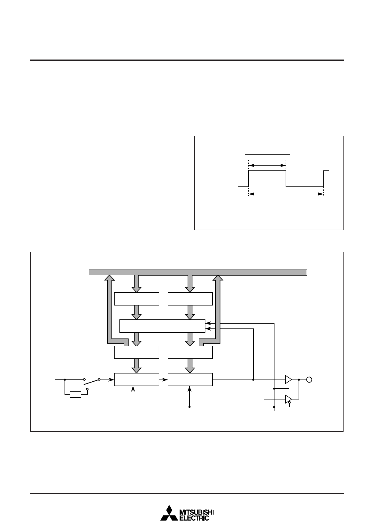
31.875 ! m ! (n+1) µs
255
PWM output
T = [31.875 ! (n+1)] µs
m: Contents of PWM register
n : Contents of PWM prescaler
T : PWM period (when f(X IN) = 8 MHz)
Fig. 20 Timing of PWM period
Data bus
PWM
prescaler pre-latch
PWM
register pre-latch
Transfer control circuit
PWM
prescaler latch
Count source
selection bit
“0”
XIN
PWM prescaler
1/2 “1”
PWM
register latch
PWM register
Fig. 21 Block diagram of PWM function
Port P44
Port P44 latch
PWM enable bit
21
Share Link: 