LX550 데이터 시트보기 (PDF) - Artesyn Technologies
부품명
상세내역
일치하는 목록
LX550 Datasheet PDF : 4 Pages
| |||
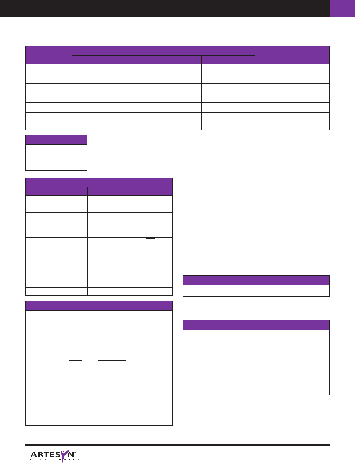
AC/DC POWER SUPPLIES | 550W AC
550 Watt
AC/DC universal input switch mode power supplies
OUTPUT
VOLTAGE
+5.0V
–5.0V
–12.0V
+12.0V
+24.0V
24.0V (4)
48.0V (4)
OUTPUT CURRENTS
MAX (1)
PEAK (2)
60.0A
100.0A
5.0A
10.0A
5.0A
10.0A
10.0A
20.0A
5.0A
10.0A
24.0A
–
12.0A
–
INPUT CONNECTIONS
Pin 1
Earth
Pin 2
Neutral
Pin 3
Live
OUTPUT CONNECTIONS
MULTI O/P SINGLE O/P
SIGNALS
1
+5VS
0VS
SRS
2
+5V
0V
ACF
3
+5V
0V
DCF
4
+5V
0V
PM
5
0V
0V
PS
6
0V
0V
ROF
7
0V
+V
+VS
8
–5V
+V
0V
9
–12V
+V
–
10
+12V
+V
–
11
+24V
+VS
–
12
ROF
ROF
–
OUTPUT RIPPLE
RMS
PK-PK
MODEL NUMBER
0.2%
2.0%
LX550-7620
0.2%
2.0%
0.2%
2.0%
0.2%
2.0%
0.2%
2.0%
0.1%
1.0%
LX550-7624
0.1%
1.0%
LX550-7617
Notes:
1 The multiple output LX550 has a continuous output power rating of 550W.
The single-output versions have a continuous power output rating of
570W. The LX550 cannot operate without fan cooling.
2 Peak power figures for individual outputs on the multiple output unit are
for less than 10 seconds duration. Total output power should not exceed
550W.
3 Fan fitted as standard, see maximum output current specifications.
4 Single output models are adjustable -8%, +16%.
5 A 10% load on the main output is necessary to maintain regulation on the
auxiliaries at full load (multiple output model).
6 The input board is fitted with an autorange circuit as standard which
automatically senses the input voltage and switches to the appropriate
voltage range.
7 Over temperature protection is provided by a thermal switch fitted to the
main transformer. After thermal shutdown (90°C) the unit must be
powered down and the thermal switch must be allowed cool to 70°C
before power up.
8 This product is only for inclusion by professional installers within other
equipment and must not be operated as a stand alone product.
Options
• DC input models for 24V and 48V operation are detailed on page 170.
• A signals board is available as an option. To order, add the suffix ‘-S’, see
table below.
OPTIONS
None
Signals
SUFFIX
-S
EXAMPLE
LX550-7620
LX550-7620-S
OVERLOAD/SHORT CIRCUIT PROTECTION
The overload/short circuit protection mechanisms are different for the single
output models and the multiple output model.
The single output models will current limit when the output load reaches
105-120% of maximum load during overload or short circuit conditions.
The unit will operate in a constant current mode making the single output
models suitable for battery charging applications.
The multiple output model uses a power limiting function. When the total
output power reaches 600W the outputs will foldback to the values detailed
below:
Output
Foldback Value
+5V
30A continuous
+12V
8A continuous
+24V
4A continuous
–5V/–12V Protected by 4A Multi Fuse™
The outputs will not foldback until the total output power exceeds the maxi-
mum power limits. This allows the units to have a peak power capability
but it requires that care must be taken not to permanently overload any
individual output. The +5V, +12V and +24V outputs are not individually pro-
tected and it is recommended that the maximum continuous load does not
exceed the value given in the output specifications. The -5V and -12V out-
puts are individually protected by a 4A Multi Fuse™ and the maximum con-
tinuous load should not exceed the value given in the output specifications.
SIGNALS (OPTIONAL)
An optional signals board supplies the following VME utility bus signals:
ACF (AC Fail) Logic 1 to 0 transition occurs >10ms before outputs fall
below 90% of nominal in the event of input failure.
DCF (DC Fail) Logic 0 occurs if output falls below <85%–95% of nominal.
SRS (System Reset) Logic 1 for system OK (AC and DC good and reset
times [200ms])
PM Power Monitor signal, proportional to the output power, ratio of
10mV/W.
PS Power Share connections, to be joined for parallel operation of two
or more units, ensuring equal power share. For power share
operation unit outputs need to be set to ±5% of each other and
should be connected in star configurations with the load as star
centre.
http://www.artesyn.com
PAGE 2
Share Link: 