3433EFE 데이터 시트보기 (PDF) - Linear Technology
부품명
상세내역
일치하는 목록
3433EFE Datasheet PDF : 16 Pages
| |||
LT3433
APPLICATIO S I FOR ATIO
Design Example
4V-60V to 5V DC/DC converter (the application on the
front page of this data sheet), load capability for TA = 85°C.
Application Specific
Constants:
LT3433 W/C Constants:
VIN = 4V
VOUT = 5V
L = 100µH
RL = 0.28Ω
VF1 = 0.45V
VF2 = 0.4V
RCESR = 0.01Ω
IMAX = 0.55A
RSWH = 1.2Ω
RSWL = 1Ω
fO = 190kHz
∆BST = 0.05
∆OUT = 0.05
IVIN = 600µA
IBIAS = 800µA
The LT3433 operates in bridged mode with VIN = 4V, so the
relations used are:
DC = [VOUT + VF1 + VF2 – ISW • (RL + RESR)]/[VIN –
ISW • (RSWH + RSWL + 2RL + RESR) + VOUT + VF1 +
VF2]
∆I = (VOUT + VF1 + VF2 - ISW • RL) • (1 – DC)/(L • fO)
IOUT(MAX) = ISW • [1 – DC • (1 + ∆BST + ∆OUT)] – IBIAS
Iteration procedure for DC:
(1) Set initial seed value for ∆I (this example will set
∆I = 0).
(2) Using seed value for ∆I, determine ISW (ISW = 0.55 –
0 = 0.55).
(3) Use calculated ISW and above design constants to
solve the DC relation (DC = 0.683).
(4) Use calculated DC to solve the ∆I relation (yields ∆I =
0.0949).
(5) If calculated ∆I is equal to the seed value, stop.
Otherwise, use calculated ∆I as new seed value and
repeat (2) through (4).
ITERATION #
1
2
3
SEED ∆I
0
0.095
0.098
CALCULATED VALUES
ISW
DC
∆I
0.55
0.683
0.095
0.503
0.674
0.098
0.501
0.674
0.098
After iteration, DC = 0.674 and ∆I = 0.098.
Use iteration result for DC and above design constants to
solve the IOUT(MAX) relation:
IOUT(MAX) = 0.501 • [1 – 0.674 • (1 + 0.05 + 0.05)] –
800µA
IOUT(MAX) = 129mA
Increased Output Voltages
The LT3433 can be used in converter applications with
output voltages from 3.3V through 20V, but as converter
output voltages increase, output current and duty cycle
limitations prevent operation with VIN at the extreme low
end of the LT3433 operational range. When a converter
operates as a buck/boost, the output current becomes
discontinuous, which reduces output current capability by
roughly a factor of 1 – DC, where DC = duty cycle. As such,
the output current requirement dictates a minimum input
voltage where output regulation can be maintained.
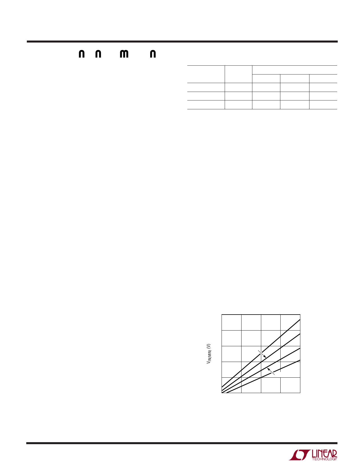
Typical Minimum Input Voltage as a Function of
Output Voltage and Required Load Current
24
20
200mA
16
175mA
12
125mA
8
150mA
4
4
8
12
16
20
VOUT (V)
3433 AI03
3433f
12
Share Link: 