K8AB-AS 데이터 시트보기 (PDF) - OMRON Corporation
부품명
상세내역
일치하는 목록
K8AB-AS Datasheet PDF : 10 Pages
| |||
■ Operation and Setting Methods
K8AB-AS
Setting Ranges and Wiring Connections
Model
K8AB-AS1
K8AB-AS2
K8AB-AS3
Measuring current
2 to 20 mA AC/DC
10 to 100 mA AC/DC
50 to 500 mA AC/DC
0.1 to 1 A AC/DC
0.5 to 5 A AC/DC
0.8 to 8 A AC/DC
10 to 100 A AC (See note 2.)
20 to 200 A AC (See note 2.)
Wiring
connection
I1-COM
I2-COM
I3-COM
I1-COM
I2-COM
I3-COM
I2-COM
I3-COM
Note: 1. The DC input terminals have no polarity.
2. The K8AB-AS3 is designed to be used in combination with
the OMRON K8AC-CT200L Current Transformer (CT).
(Direct input is not possible.)
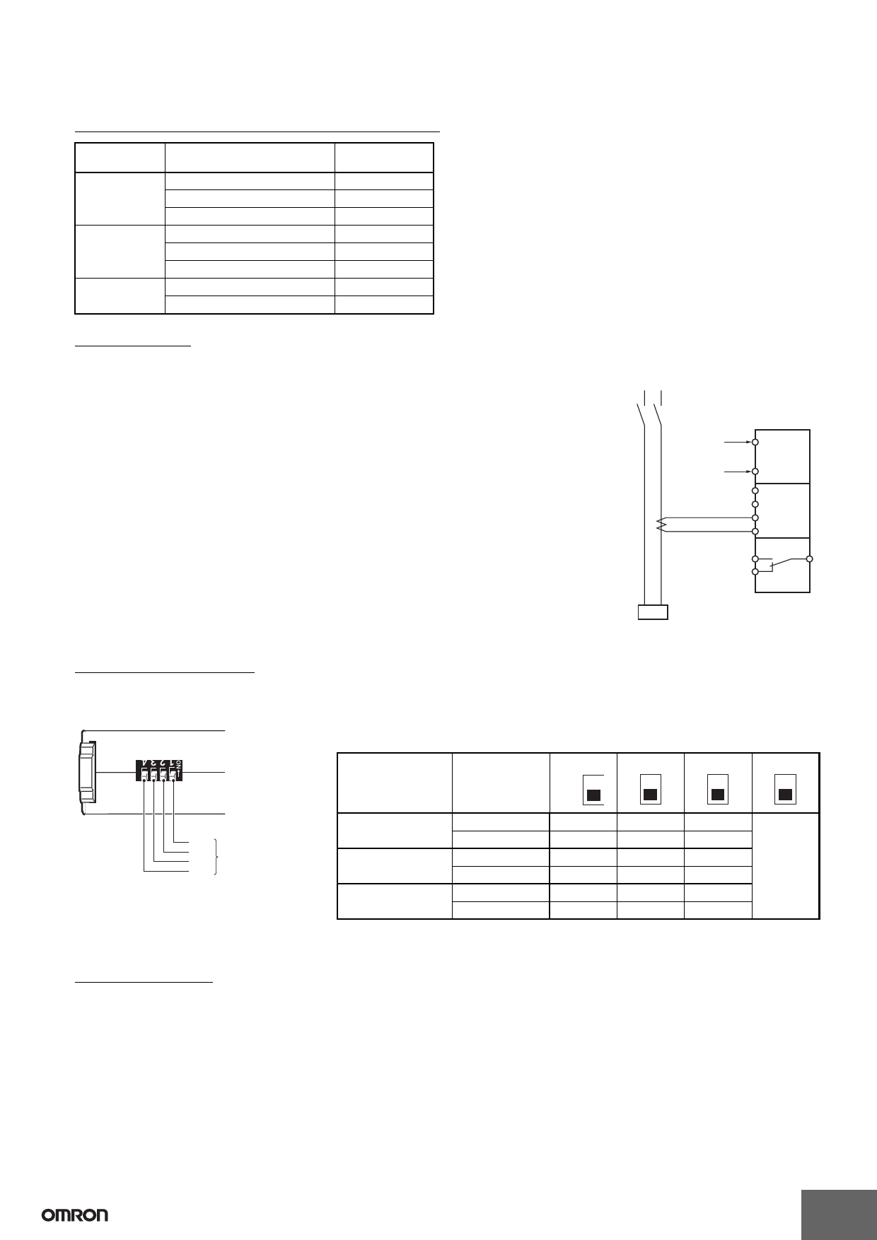
Connections
1. Input
Connect the input between the I1-COM, I2-COM, or I3-COM terminals, according to the input
current. Malfunctions may occur if the input is connected to unused terminals and the Unit will
not operate correctly.
Terminal I1 is not used by the K8AB-AS3.
If using the OMRON K8AC-CT200L CT, connect to terminals k and l on the K8AC-CT200L.
(Terminals kt and lt are not used.)
2. Power Supply
Connect the power supply to terminals A1 and A2.
3. Outputs
SPDT relays are output to terminals 11, 12, and 14.
Note: Use the recommended ferrules if using twisted wires.
<For K8AB-AS3>
Single-phase power
K8AB-AS3
Power supply
voltage
K8AC-
CT200L
k
Current input
l
A1
A2
I1
I2
I3
COM
14
Signal output
12
11
Relay
signal
output
Load
DIP Switch Settings
The resetting method, relay drive method, and operating mode are set using the DIP switch located on the bottom of the Unit.
K8AB-AS@ does not use SW1.
ON
OFF
SW1
SW2
SW3
SW4
DIP switch
DIP Switch Functions
SWITCH
ON ● ↑
4
3
2
ON
OFF ❍ ↓ OFF
Resetting method Automatic reset
---
---
●
Manual reset
---
---
❍
Relay drive method Normally closed
---
●
---
Normally open
---
❍
---
Operating mode Undercurrent
●
---
---
Overcurrent
❍
---
---
Note: All pins are set to OFF at the factory.
1
NO USE
Setting Method
1. Setting Current
The current knob (SV) is used to set the current.
The current can be set to 10% to 100% of the maximum measuring current.
Turn the knob while there is an input to the input terminals until the alarm indicator flashes (when the set value and the input have reached the
same level.)
Use this as a guide to set the current.
The maximum measuring current will differ depending on the model and the input terminal.
Example: K8AB-AS3 Using Input Terminals I3-COM
The maximum measuring current will be 200 A AC and the setting range will be 20 to 200 A.
7
Share Link: 