ISL6244 데이터 시트보기 (PDF) - Intersil
부품명
상세내역
일치하는 목록
ISL6244 Datasheet PDF : 25 Pages
| |||
ISL6244
Interleaving
The switching of each channel in a multi-phase converter is
timed to be symmetrically out of phase with each of the other
channels. In a 3-phase converter, each channel switches 1/3
cycle after the previous channel and 1/3 cycle before the
following channel. As a result, the three-phase converter has
a combined ripple frequency three times greater than the
ripple frequency of any one phase. In addition, the peak-to-
peak amplitude of the combined inductor currents is reduced
in proportion to the number of phases (Equations 1 and 2).
Increased ripple frequency and lower ripple amplitude mean
that the designer can use less per-channel inductance and
lower total output capacitance for any performance
specification.
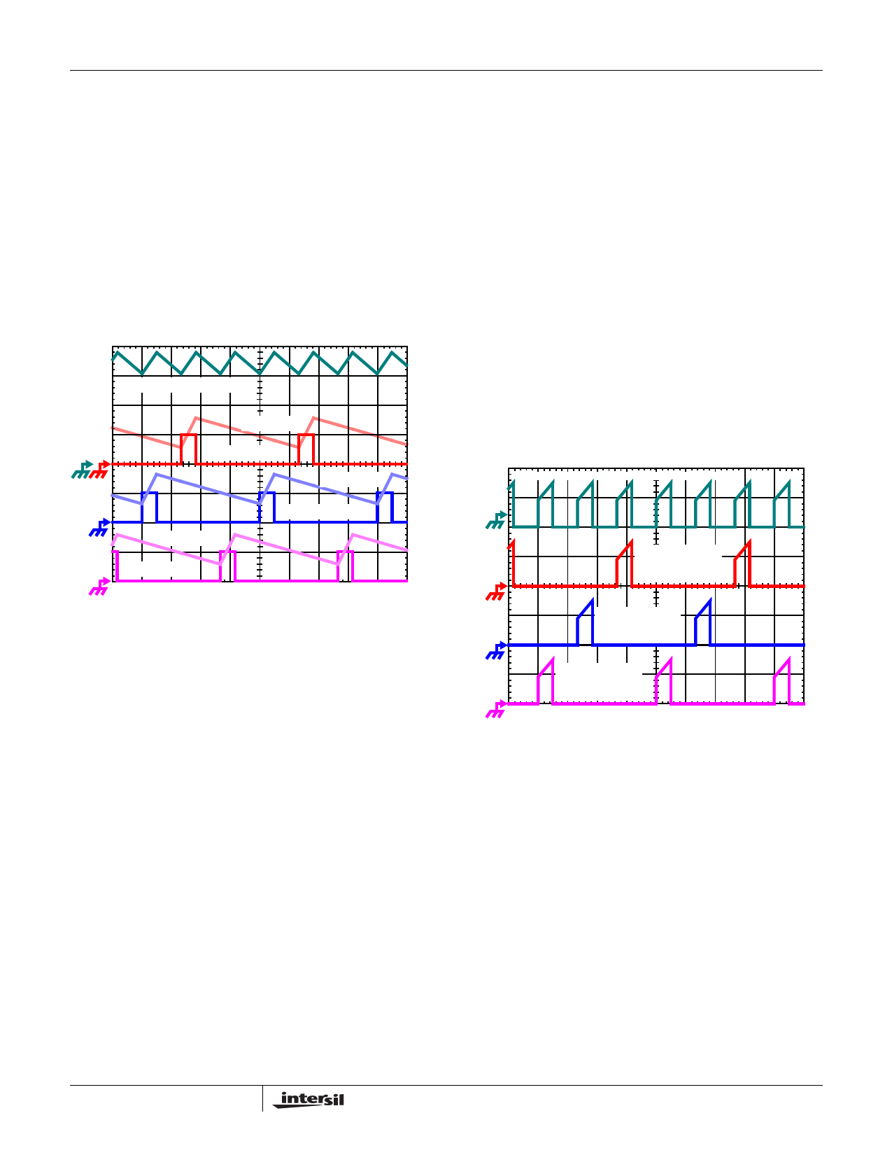
IL1 + IL2 + IL3, 7A/DIV
IL3, 7A/DIV
PWM3, 5V/DIV
IL2, 7A/DIV
IL1, 7A/DIV
PWM2, 5V/DIV
PWM1, 5V/DIV
1µs/DIV
FIGURE 13. PWM AND INDUCTOR-CURRENT WAVEFORMS
FOR 3-PHASE CONVERTER
Figure 13 illustrates the multiplicative effect on output ripple
frequency. The three channel currents (IL1, IL2, and IL3),
combine to form the AC ripple current and the DC load
current. The ripple component has three times the ripple
frequency of each individual channel current. Each PWM
pulse is terminated 1/3 of a cycle, or 1.33µs for fS = 250kHz,
after the PWM pulse of the previous phase. The peak-to-peak
current waveforms for each phase is about 7A, and the dc
components of the inductor currents combine to feed the load.
To understand the reduction of ripple current amplitude in the
multi-phase circuit, examine the equation representing an
individual channel’s peak-to-peak inductor current.
IPP =
(---V----I--N-----–-----V----O-----U----T---)----V----O----U-----T-
L fS VIN
(EQ. 1)
In Equation 1, VIN and VOUT are the input and output
voltages respectively, L is the single-channel inductor value,
and fS is the switching frequency.
The output capacitors conduct the ripple component of the
inductor current. In the case of multi-phase converters, the
capacitor current is the sum of the ripple currents from each
of the individual channels. Compare Equation 1 to the
expression for the peak-to-peak current after the summation
of N symmetrically phase-shifted inductor currents in
Equation 2. Peak-to-peak ripple current decreases by an
amount proportional to the number of channels. Output-
voltage ripple is a function of capacitance, capacitor
equivalent series resistance (ESR), and inductor ripple
current. Reducing the inductor ripple current allows the
designer to use fewer or less costly output capacitors.
IC, PP=
(---V----I--N-----–-----N------V----O-----U----T---)----V----O----U-----T-
L fS VIN
(EQ. 2)
Another benefit of interleaving is to reduce input ripple
current. Input capacitance is determined in part by the
maximum input ripple current. Multi-phase topologies can
improve overall system cost and size by lowering input ripple
current and allowing the designer to reduce the cost of input
capacitance. The example in Figure 14 illustrates input
currents from a three-phase converter combining to reduce
the total input ripple current.
INPUT-CAPACITOR CURRENT, 15A/DIV
CHANNEL 3
INPUT CURRENT
15A/DIV
CHANNEL 2
INPUT CURRENT
15A/DIV
CHANNEL 1
INPUT CURRENT
15A/DIV
1µs/DIV
FIGURE 14. CHANNEL INPUT CURRENTS AND INPUT-
CAPACITOR RMS CURRENT FOR 3-PHASE
CONVERTER
The converter depicted in Figure 14 delivers 52A to a 1.20V
load from a 19V input. The RMS input capacitor current is
6.5A. Compare this to a single-phase converter also
stepping down 19V to 1.20V at 52A. The single-phase
converter has 11.96A RMS input capacitor current. The
single-phase converter must use an input capacitor bank
with twice the RMS current capacity as the equivalent three-
phase converter.
Figures 28, 29 and 30 in the section entitled Input Capacitor
Selection can be used to determine the input-capacitor RMS
current based on load current, duty cycle, and the number of
channels. They are provided as aids in determining the
optimal input capacitor solution. Figure 31 shows the single
phase input-capacitor RMS current for comparison.
10
FN9106.3
December 28, 2004
Share Link: 