L6918 데이터 시트보기 (PDF) - STMicroelectronics
부품명
상세내역
일치하는 목록
L6918 Datasheet PDF : 35 Pages
| |||
L6918 L6918A
DEVICES DESCRIPTION
The devices are integrated circuit realized in BCD technology. They provide, in kit, a complete control logic and
protections sets for a high performance four-phases step-down DC-DC converter optimized for microprocessors
supply and High Density DC-DC converters. They are designed to drive N-Channel mosfets in an interleaved
four-phase synchronous-rectified buck topology. Each controller provides a 180 deg phase shift between its two
phases and a 90deg phase-shifted synchronization signal is passed from the master to the slave controller that
locks the signal through a PLL. The resulting four-phases converter synchronized together results in a 90 deg
phase shift on each phase, allowing a consistent reduction of the input capacitors ripple current, minimizing also
the size and the power losses. The output voltage of the converter can be precisely regulated, programming the
master's VID pins, from 1.100V to 1.850V with 25mV binary steps. The reference for the regulation is passed
from the master device to the slave device through apposite pin likewise the synchronization signal. Each device
provides an average current-mode control with fast transient response. They include a 300kHz free-running os-
cillator externally adjustable up to 600kHz, realized in order to multiply by 4 times the equivalent system fre-
quency. The error amplifier features a 15MHz gain-bandwidth product and 10V/µs slew rate that permits high
converter bandwidth for fast transient performances. Current information is read in all the devices across the
lower mosfets RDSON or across a sense resistor in fully differential mode. The current information corrects the
PWM output in order to equalize the average current carried the two phases of each device. Current sharing
between the two phases of each device is then limited at ±10% over static and dynamic conditions. Current
sharing between devices is assured by the droop function. The device protects against over-current, with an
OCP threshold for each phase, entering in constant current mode. Since the current is read across the low side
mosfets, the constant current keeps constant the bottom of the inductors current triangular waveform. When an
under voltage is detected the Slave device latches. The Slave device also perform an over voltage protection
that disable immediately both devices turning ON the lower driver and driving high the FAULT pin. Over Load
condition are transmitted from the Slave device(s) to the master through the SLAVE_OK line.
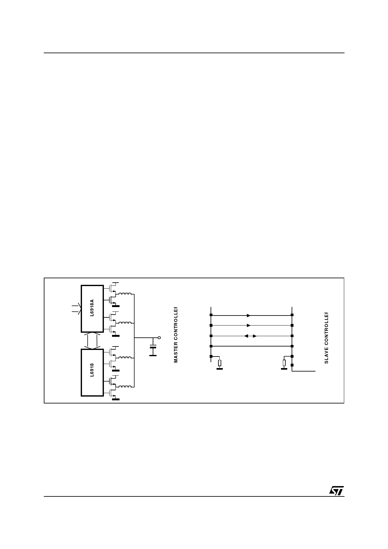
MASTER - SLAVE INTERACTIONS
Figure 1. Four Phase connection with L6918 family
VID 9.0
SYNC_OUT
VPROG_OUT
SLAVE_OK
PGOOD
OSC
SYNC_IN
V PR O G _ IN
SLAVE_OK
PGOOD
OSC
SYNC_OUT
Master and slave devices are connected together in order to realize four-phase high performance step-down
DC/DC converter. Four-phase converter is implemented using L6918A master and one L6918 slave devices as
shown in figure 1.
A communication bus is implemented among all the controllers involved in the regulation. This bus consists in
the following lines:
– Reference (VPROG_IN / VPROG_OUT pins): Unidirectional line.
The devices share the reference for the regulation. The reference is programmed through the master
device VID pins. It exits from the master through the VPROG_OUT pin and enters the slave device
through the VPROG_IN pin(s). Filter externally with at least 1nF capacitor.
10/35
Share Link: 