ICE2AS01 데이터 시트보기 (PDF) - Infineon Technologies
부품명
상세내역
일치하는 목록
ICE2AS01 Datasheet PDF : 24 Pages
| |||
ICE2AS01/S01G
ICE2BS01/S01G
Functional Description
3 Functional Description
3.1
Power Management
3.2
Improved Current Mode
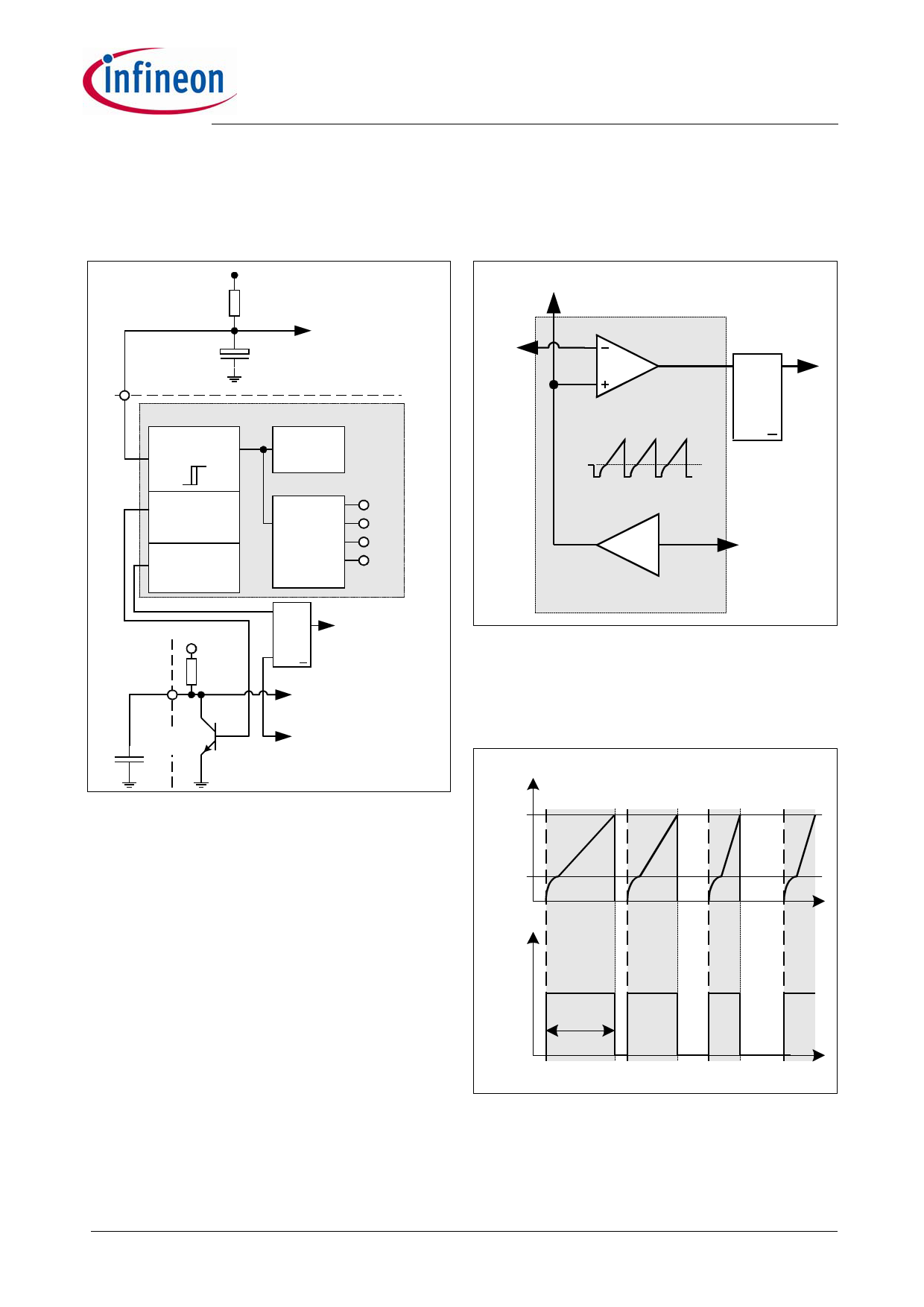
VCC
Main Line (100V-380V)
RStart-Up
CVCC
Primary Winding
Power Management
Undervoltage
Lockout
13.5V
8.5V
Internal
Bias
Power-Down
Reset
Power-Up
Reset
Voltage
Reference
6.5V
5.3V
4.8V
4.0V
SoftS
6.5V
RSoft-Start
RQ
PWM-Latch
SQ
Error-Latch
Soft-Start Comparator
CSoft-Start
T1
Error-Detection
Soft-Start Comparator
FB
PWM-Latch
RQ
Driver
PWM Comparator
SQ
0.8V
PWM OP
x3.65
Improved
Current Mode
Isense
Figure 4 Current Mode
Current Mode means that the duty cycle is controlled
by the slope of the primary current. This is done by
comparison the FB signal with the amplified current
sense signal.
Amplified Current Signal
Figure 3 Power Management
The Undervoltage Lockout monitors the external
supply voltage VVCC. In case the IC is inactive the
current consumption is max. 55µA. When the SMPS is
plugged to the main line the current through RStart-up
charges the external Capacitor CVCC. When VVCC
exceeds the on-threshold VCCon=13.5V the internal bias
circuit and the voltage reference are switched on. After
it the internal bandgap generates a reference voltage
VREF=6.5V to supply the internal circuits. To avoid
uncontrolled ringing at switch-on a hysteresis is
implemented which means that switch-off is only after
active mode when Vcc falls below 8.5V.
In case of switch-on a Power Up Reset is done by
reseting the internal error-latch in the protection unit.
When VVCC falls below the off-threshold VCCoff=8.5V the
internal reference is switched off and the Power Down
reset let T1 discharging the soft-start capacitor CSoft-Start
at pin SoftS. Thus it is ensured that at every switch-on
the voltage ramp at pin SoftS starts at zero.
FB
0.8V
Driver
t
Ton
t
Figure 5 Pulse Width Modulation
In case the amplified current sense signal exceeds the
FB signal the on-time Ton of the driver is finished by
reseting the PWM-Latch (see Figure 5).
Datasheet
7
Preliminary Data
30 Jun 2006
Share Link: 