HF15-226ETZ 데이터 시트보기 (PDF) - Avago Technologies
부품명
상세내역
일치하는 목록
HF15-226ETZ Datasheet PDF : 16 Pages
| |||
Transmitter Electrical/Optical Characteristics -40° to 85° C unless otherwise specified.
Parameter
Transmitter Output
Optical Power
Output Optical Power
Temperature Coefficient
Peak Emission
Wavelength
Forward Voltage
Forward Voltage
Temperature Coefficient
Effective Diameter
Reverse Input Breakdown
Voltage
Diode Capacitance
Rise Time
Fall Time
Symbol
PT
PT/T
PK
VF
VF/T
D
VBR
CO
tr
tf
Min. Typ.[5] Max. Units
Conditions
-16.8
-7.1 dBm IFdc = 60 mA
-14.3
-8.0 dBm IFdc = 60 mA, 25° C
-0.85
%/°C
660
nm
1.43 1.67
-1.37
2.05
V
IFdc = 60 mA
mV/°C
1
5.0 11.0
86
20
20
mm
V
IFdc = 10 A,
TA = 25° C
pF VF = 0, f = MHz
ns 10% to 90%,
ns IF = 60 mA
Ref.
Notes 1, 2
Fig. 7
Note 3
Notes:
1. Optical power measured at the end of 0.5 m of 1 mm diameter POF (NA = 0.5) with a large area detector.
2. Optical power, P (dBm) = 10 Log [P(W)/1000 W].
3. Rise and fall times are measured with a voltage pulse driving the transmitter driver IC (75451). A wide bandwidth optical to electrical waveform
analyzer, terminated to a 50 input of a wide bandwidth oscilloscope, is used for this response time measurement.
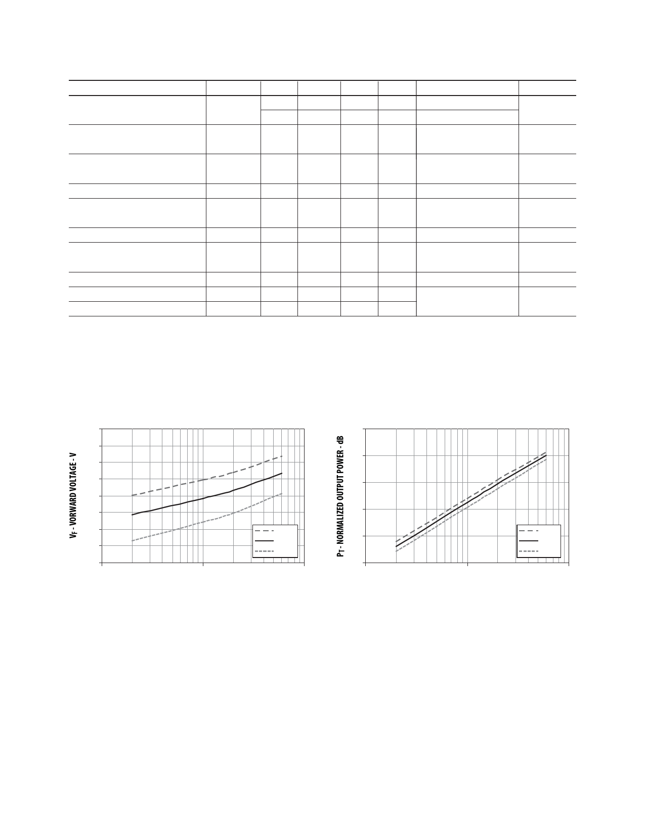
1.8
1.75
1.7
1.65
1.6
1.55
1.5
1.45
1.4
1
-40° C
25° C
85° C
10
100
IFdc - TRANSMITTER DRIVE CURRENT (mA)
Figure 7. Typical forward voltage vs. drive current
5
0
-5
-10
-15
-40° C
25° C
85° C
-20
1
10
100
IFdc - TRANSMITTER DRIVE CURRENT (mA)
Figure 8. Normalized typical output power vs. drive current
10
Share Link: 