GM19371 데이터 시트보기 (PDF) - Gamma Microelectronics Inc.
부품명
상세내역
일치하는 목록
GM19371 Datasheet PDF : 10 Pages
| |||
GM19371
BOOST WHITE LED DRIVER
WITH OVP
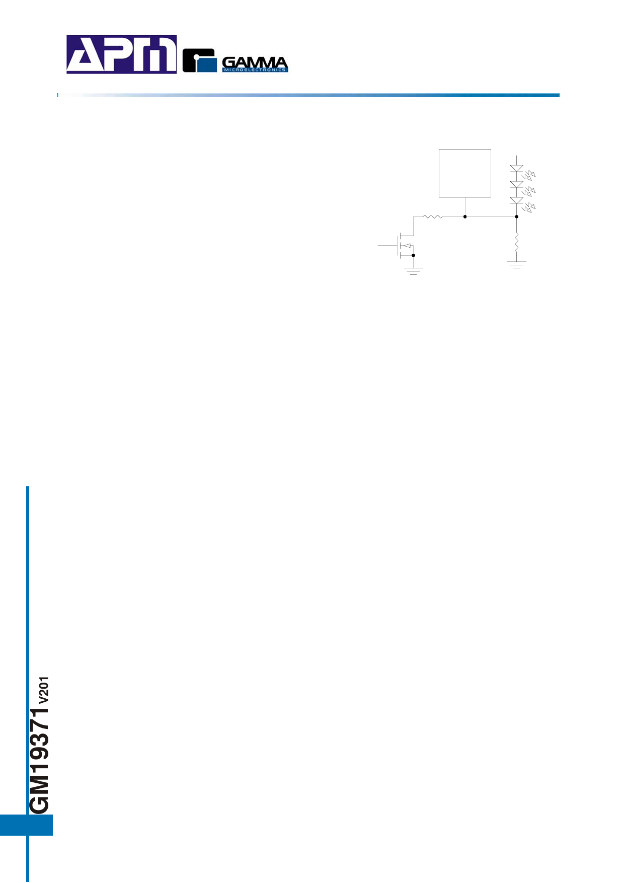
4. Using a Logic Signal
For applications that need to adjust the LED current in
discrete steps, a logic signal can be used as shown in
figure 8. RSET sets the minimum LED current (when the
NMOS is off). RINC sets how much the LED current
increases when the NMOS is turned on. The selection
of RSET and RINC follows the formula and Table in “LED
Current Control” section.
Logic Signal
GM19371
RINC
Figure 8
RSET
6.3Ω
Board Layout Consideration
As with all switching regulators, careful attention must be paid to the PCB board layout and component
placement. To maximize efficiency, the rising and falling times of the switch are made as short as possible.
To prevent electromagnetic interference (EMI) problems, proper layout of the high frequency switching path
is essential. The voltage signal of the SW pin has sharp rising and falling edges. Minimize the length and
area of all traces connected to the SW pin and always use a ground plane under the switching regulator to
minimize inter-plane coupling. In addition, the ground connection for the feedback resistor RSET should be
tied directly to the GND pin and not shared with any other component, ensuring a clean, noise-free
connection.
8
Share Link: 