G9105 데이터 시트보기 (PDF) - Global Mixed-mode Technology Inc
부품명
상세내역
일치하는 목록
G9105 Datasheet PDF : 9 Pages
| |||
Global Mixed-mode Technology Inc.
G9105
Absolute Maximum Ratings
(Note 1)
Input Voltage. . . . . . . . . . . . . . . . . . . . . . . . . . . . . . .8V
VEN Voltage . . . . . . . . . . . . . . . . . . . . . . . . . . . . . . . 8V
Power Dissipation Internally Limited
(Note 2)
Maximum Junction Temperature . . . . . . . . . . . . . . 150°C
Storage Temperature Range. . . . .-65°C ≤ TJ ≤+150°C
Reflow Temperature (soldering, 10 sec) . . . . . . 260°C
Continuous Power Dissipation (TA = +25°C)
TO-220F-4 No Heatsink . . . . . . . . . . . . . . . . .80°C/W
TO-220F-4 with Infinite Heatsink . . . . . . . . . . 36°C/W
Thermal Resistance Junction to Ambient, (θJA)
SOP-8. . . . . . . . . . . . . . . . . . . . . . . . . . . . . .180°C/W
Operating Conditions
(Note 1)
Input Voltage . . . . . . . . . . . . . . . . . . . . . . . . . . 5.5V~7V
Temperature Range. . . . . . . . . . . . . . -20°C ≤ TA ≤85°C
VEN Voltage . . . . . . . . . . . . . . . . . . . . . . . . . . .VIN+0.3V
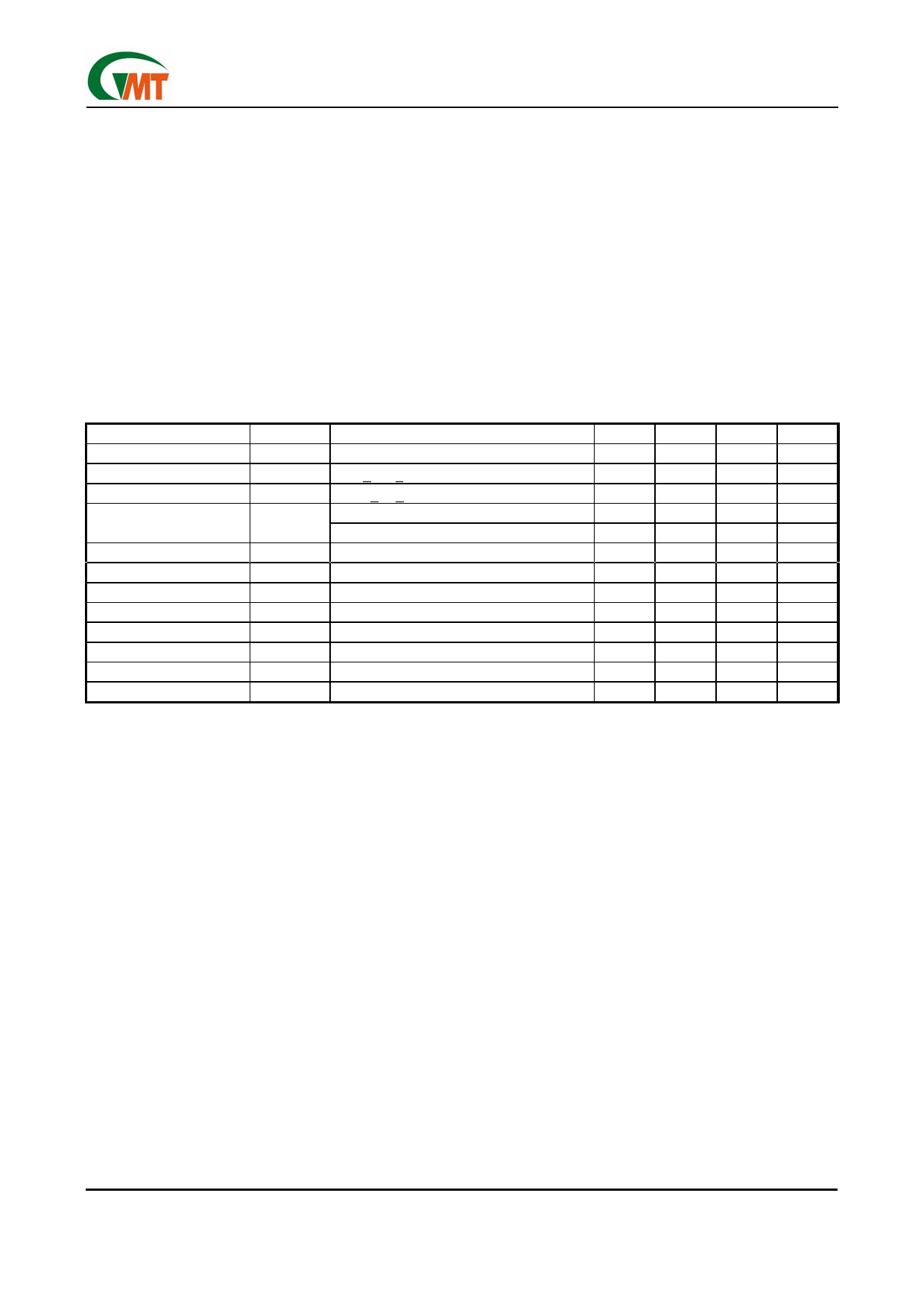
Electrical Characteristics
VIN =7V, IO = 0.5A, CIN = 4.7µF, COUT =47µF, TA = TJ = 25°C unless otherwise specified [Note 3]
PARAMETER
Output Voltage
Line Regulation
Load Regulation
Quiescent Current
Ripple Rejection
Dropout Voltage
Short Circuit Current
Over Temperature
VEN Voltage High
VEN Voltage Low
VEN Bias Current High
VEN Bias Current Low
SYMBOL
CONDITION
VO
IO = 0.5A
5.5V < VIN < 7V, IO = 10mA
50mA < IO < 1A
IQ
VIN = 5.5V, VEN = VIN
VIN = 5.5V, VEN = 0V
fi = 120Hz, 1VP-P, IO = 100mA
VD
IO = 1A
VENH
VENL
IENH
IENL
Output Active
Output Disabled
VEN = 2.7V
VEN = 0.4V
MIN
4.875
---
---
---
---
---
---
---
---
2
---
---
---
TYP
5
0.5
0.5
5
10
35
---
1.9
150
---
---
---
---
MAX
5.125
2
2
10
30
---
0.5
---
---
---
0.8
20
20
UNIT
V
%
%
mA
µA
dB
V
A
°C
V
V
µA
µA
Note 1:
Note2:
Note3:
Note4:
Absolute Maximum Ratings are limits beyond which damage to the device may occur. Operating Conditions are
conditions under which the device functions but the specifications might not be guaranteed. For guaranteed specifications
and test conditions see the Electrical Characteristics.
The maximum power dissipation is a function of the maximum junction temperature, TJmax ; total thermal resistance,
θJA, and ambient temperature TA. The maximum allowable power dissipation at any ambient temperature is Tjmax-TA /
θJA. If this dissipation is exceeded, the die temperature will rise above 150°C and IC will go into thermal shutdown. For
the TO-220F-4 package, θJA is 80°C/W (No heat sink).
Low duty pulse techniques are used during test to maintain junction temperature as close to ambient as possible.
The type of output capacitor should be tantalum or aluminum.
Definitions
Dropout Voltage
The input/output Voltage differential at which the regu-
lator output no longer maintains regulation against fur-
ther reductions in input voltage. Measured when the
output drops 2% below its nominal value, dropout volt-
age is affected by junction temperature, load current
and minimum input supply requirements.
Line Regulation
The change in output voltage for a change in input
voltage. The measurement is made under conditions of
low dissipation or by using pulse techniques such that
average chip temperature is not significantly affected.
Load Regulation
The change in output voltage for a change in load
current at constant chip temperature. The measure-
ment is made under conditions of low dissipation or
by using pulse techniques such that average chip
temperature is not significantly affected.
Maximum Power Dissipation
The maximum total device dissipation for which the
regulator will operate within specifications.
Quiescent Bias Current
Current which is used to operate the regulator chip
and is not delivered to the load.
Ver: 0.9 Preliminary
Jul 07, 2006
TEL: 886-3-5788833
http://www.gmt.com.tw
2
Share Link: 