FAN8038C 데이터 시트보기 (PDF) - Fairchild Semiconductor
부품명
상세내역
일치하는 목록
FAN8038C Datasheet PDF : 16 Pages
| |||
FAN8038C
Application Information
1. BAKE AND MUTE FUNCTION
• Of the four channel drivers, channel 1 has a brake function, and the other channels have a mute function.
• When the BRAKE (pin23) is set to high level, both channel 1 outputs go low level. (Brake mode).
• When the MUTE2 (pin21) is set to high level, the channel 2 output is muted.
• When the MUTE34 (pin19) is set to high level, the channel 3 and 4 outputs are muted.
•
2. REFERENCE VOLTAGE(VREF) DROP MUTE
• When the voltage applied to VREF (pin16) is 1.0V or less (typical), the H-bridge driver outputs are set to high impedance.
3. THERMAL SHUTDOWN (TSD)
• If the chip temperature reaches 150°C (typical), the H-bridge driver output current is cut-off and the thermal shut down
circuit has a hysteresis temperature of 25°C.
4. H-BRIDGE DRIVER (4-CHANNELS)
• The driver input resistance is 11KΩ(typical) for channels 1, 3 , and 4, and 7.5KΩ for channel 2. Set the gain according to
the following formula.
•
Channel
Gain
Unit
CH1
CH3
Gv = 20log 55K
dB
CH4
11K + REXT
CH2
Gv = 20log 110K
dB
7.5K + REXT
where, REXT is externally connected input resistance.
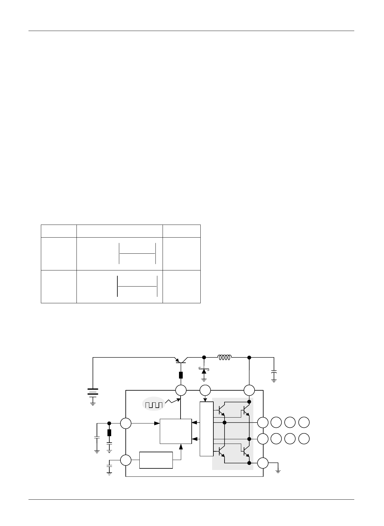
5. SWITCHING REGULATED POWER SUPPLY DRIVE
• The power supply of H-bridge driver consists of DVCC(pin36) for output stage power supply and VSYS2 (pin15) for
predriver power supply.
VBAT
37
15
36
PWM
44
Maximum
Pre-
driver
Detector
9
Triangular
Waveform
25 27 29 31
24 26 30 32
28
Figure 1. Switching Regulated Power Supply
10
Share Link: 