FAN8001 데이터 시트보기 (PDF) - Fairchild Semiconductor
부품명
상세내역
일치하는 목록
FAN8001 Datasheet PDF : 14 Pages
| |||
FAN8001D
3. REGULATOR
I
VREF BG
−
+
D1
R1
D2
5
KSB772
6
VOUT
(5V)
R2
+
CE
R3
100µF
• The VREF BG is the output voltage of the band-gap-referenced biasing circuit and is the reference voltage of the regulator.
• The external circuit is composed of the transistor, KSB772 and a capacitor, 100µF, and the capacitor is used as a ripple filter
and should have a good temperature characteristics.
• The output voltage, VOUT is determined as follows.
VOUT = VREF BG × 2 = 2.5 × 2 = 5V (R2 = R3)
R2 = R3
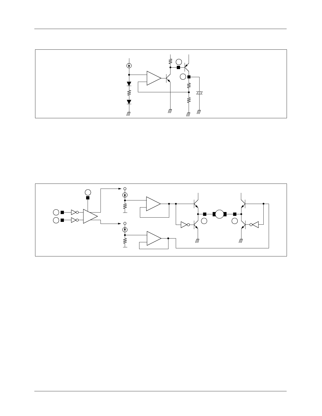
4. LOADING MOTOR DRIVER
20
I
+∆V
+ Buffer
COMP
R
−
9
+
VREF1
14
−
I
−∆V
R
VREF1
Buffer
+
−
Q1 −∆V
M
15
Q3
+∆V Q2
16
Q4
• The input voltages of (5V and 0V) or (0V and 5V) pairs are applied to the input pin #9 and #14 respectively.
• When the input voltages are applied to the input pin #9 and #14, then the output of the comparator is decided depends on the
input voltage status.
• As shown in the above diagram, the difference ∆V, [VREF1 + (I × R)] - [VREF1 -(I × R)], is applied to the both terminals of
the motor. The direction of the motor is decided by the voltage difference, +∆V and −∆V.
• The output characteristics is as follows,
- If pin # 9=5V and #14=0V, then pin # 15=+∆V and #16= −∆V, hence the motor turn in forward direction.
- If pin # 9=0V and #14=5V, then pin # 15= −∆V and #16=+∆V, hence the motor turn in reverse direction.
- If pin # 9=5V and #14=5V, then ∆V=0V, hence the motor stop.
- If pin # 9=0V and #14=0V, then ∆V=0V, hence the motor stop.
• When the rotation speed control of the loading motor is desired, refer to the follows.
8
Share Link: 