FAN7532 데이터 시트보기 (PDF) - Fairchild Semiconductor
부품명
상세내역
일치하는 목록
FAN7532 Datasheet PDF : 16 Pages
| |||
Application Information
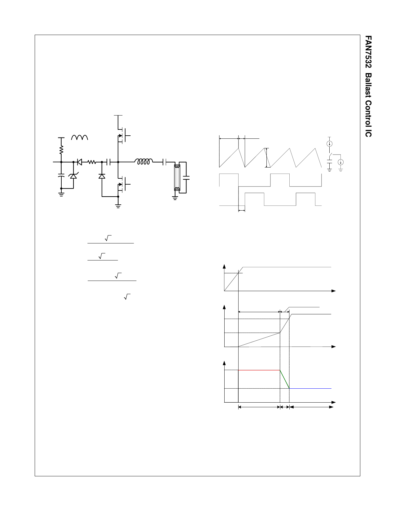
1. Start-up Circuit
The start-up current is supplied to the IC through the
start-up resistor (Rst). To reduce the power dissipation in
Rst, Rst is connected to the full-wave, rectified output
voltage. The size of Rst can be determined by equations
(1) and (2).
DC 400V
3. Oscillator
The gate drive output frequency is half that of the trian-
gular waveform on timing capacitor (CT) at pin #6. In
normal operating mode, the timing capacitor charging
current is 4•Irt (=Vref/RT). The discharging current is 6.2
times the charging current. During the charging period of
the timing capacitor (CT), the MOSFET alternatively
turns on. During the discharging period of the timing
capacitor (CT), both MOSFETs are off.
Rectifier
Output
Rst
D2
Vcc
M1
G1
CQ
Cs
ZD1
D1
G2
M2
FAN7532 Rev. 00
Figure 15. Start-up Circuit
Charging
Period (ΔTCH)
ICH
Discharging
Period (ΔTDIS)
IDIS=6.2∗ICH
VCT
3.45V
LO
Vref
ICH
IDIS
CT
HO
Dead Time
FAN7532 Rev. 00
Figure 16. CT & Output Waveforms
Rst
=
Vin(ac)
×
2 -Vth(st).max
Ist,max
(1)
=
85 ×
0.18
2 -12.4
× 10 -3
=599
[kΩ]
Rst
=
(Vin(ac,max) ×
Rst
2 -Vcc )2
≤ 0.5
[W]
(2)
Rst ≥ 2 × (Vin(ac,max) × 2 − Vcc )2
≥ 260 [kΩ]
∴ 260[kΩ] ≤ Rst ≤ 599[kΩ]
The size of supply capacitor (Cs) is normally determined
by the start-up time and the operating current which is
built up by the auxiliary operating current source. The
turn-off snubber capacitor (CQ) and two diodes (D1, D2)
constitute the auxiliary operating current source for the
IC. The charging current through the CQ flows into the IC
and charges the supply capacitor. If the size of CQ is
increased, the VCC voltage on the Cs is also increased.
2. Under-Voltage Lockout (UVLO)
The UVLO mode of the FAN7532 is designed to maintain
an ultra low supply current of less than 120µA, and to
guarantee that the IC is fully functional before two output
drivers are activated.
The FAN7532 has three operating modes according to
VCPH, as shown in Figure 17.
Vcc
Vth(st)
VCPH
5V
2.9V
f
fpre
frun
t
ICPHL=1.5mA
ICPHH=10mA
t
fpre
fign
frun
preheating
tph
ignition
tsw
t
run
FAN7532 Rev. 00
Figure 17. Operating Modes
© 2006 Fairchild Semiconductor Corporation
FAN7532 Rev. 1.0.2
9
www.fairchildsemi.com
Share Link: 