EM4022V11WS11 데이터 시트보기 (PDF) - EM Microelectronic - MARIN SA
부품명
상세내역
일치하는 목록
EM4022V11WS11
EM Microelectronic - MARIN SA

EM4022V11WS11 Datasheet PDF : 15 Pages
| |||
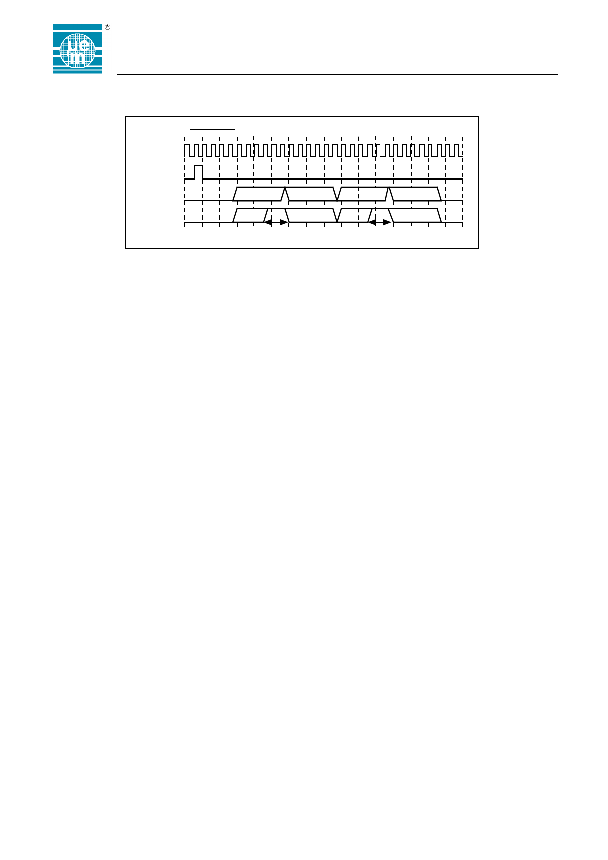
ACK timing diagram
Clock
ACK timing
Bit n
Data
HF ACK
LF ACK
T1
GAP Detection Algorithm
The GAP detection logic contains two main controllers,
one for detecting the ACK signal, and one for detecting
the MUTE and WAKE-UP signals. The WAKE-UP signal
is also called an asynchronous ACK, as it is really an
ACK meant for another chip. It also contains a pre-
processor for low frequency GAP signals.
Refer to the timing diagrams in Figure 6 and 7 for the
following detailed description of the GAP detection
algorithms.
ACK
The controller checks for a LOW 1.75 bit periods after
the last bit of code has been transmitted. It then checks
for a HIGH 3 bits later, a LOW 3 bits later and finally a
HIGH a further 3 bits later.
The reader should synchronise itself to the frequency of
the received code, check the CRC and then send two
GAPs so that the above pattern is matched. Ideally to
achieve the lowest error rate, the GAPS should be as
narrow as possible and situated 4.75 and 7.75 bits after
the last bit of code.
In practice allowance must be made for the fact that the
on-chip oscillator can drift in the time between when the
last code bit is transmitted and when the GAPs are
expected. One reason for the drift is that the oscillator is
supply voltage dependent, and the supply voltage will
typically be rising during this time, since the transponder
will not be modulating its coil or antenna.
The slope of the rising and falling edges of the GAPs can
also be adjusted to reduce reader power bandwidth. In
the case of high frequency GAPs the envelope is used
directly. Low frequency GAPs have to be pre-processed.
They are detected by checking for high periods lasting
longer than one bit period. For this reason there is a set-
up time of 1 bit. The minimum GAP width is therefore 1
bit period (T1 in the timing diagram).
EM4022
T1
Fig. 6
MUTE
The MUTE signal is received asynchronously by the
transponder. The controller checks for a HIGH less than
7 bits wide after pre-processing (T2 in the timing
diagram). As in the case of the ACK, low frequency
MUTE GAPs must be at least one bit wide (T1 in the
timing diagram), but high frequency GAPs can be
arbitrarily narrow.
When transmitting a MUTE, the reader must take into
account that there could be a spread in the clock
frequencies of all the receiving transponders.
The reader should therefor limit the width of a MUTE to
be less than 5 bits of the nominal bit rate (T4 in the timing
diagram). A low frequency MUTE should also be wider
than 1.5 bits of the nominal bit rate (T3 in the timing
diagram).
The MUTE should be sent as early as possible after a
code transmission has been detected, while still making
sure that it is a code transmission and not just noise. The
earlier the MUTE is sent, the more time the reader has to
recover before the SYNCH and code bits arrive, and the
smaller the probability that another transponder has
started a colliding transmission
Copyright 2002, EM Microelectronic-Marin SA
6
www.emmicroelectronic.com
Share Link: