ATA6621N 데이터 시트보기 (PDF) - Atmel Corporation
부품명
상세내역
일치하는 목록
ATA6621N Datasheet PDF : 28 Pages
| |||
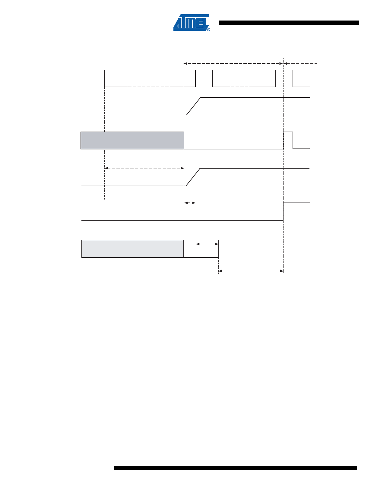
Figure 3-5. LIN Wake-up Waveform Diagram from Sleep Mode
LIN Bus
TXD
VLIN < 0.4 VS
Pre-normal Mode
Normal Mode
RXD
VCC
EN
NRES
Low or floating
Bus wake-up filtering time
tbus
Off state
Regulator wake-up time
Node in sleep mode
Low or floating
Reset
time
Low
On state
EN High
Microcontroller start-up
time delay
3.15.4
Pre-normal Mode
At system power-up the device automatically switches to Pre-normal mode. The voltage regula-
tor is switched on VCC = 5V ±2%/50 mA (see Figure 3-7 on page 13). The NRES output switches
to low for tres = 10 ms and sends a reset to the microcontroller. LIN communication is switched
off and the watchdog is active. The ATA6621N stays in this mode until EN is switched to high.
If VBattery (VS < 4V) is powered down during Silent mode or Sleep mode, the IC powers up into
Pre-normal mode. During this mode the TXD pin is an output.
3.15.5
Unpowered Mode
If you connect battery voltage to the application circuit, the voltage at the VS pin increases due
to the block capacitor (see Figure 3-7 on page 13). When VS becomes higher than the VS under-
voltage threshold VS_th, the IC mode changes from Unpowered mode to Pre-normal mode. The
VCC output voltage reaches its nominal value after tVCC. This time depends on the VCC capacitor
and the load.
The NRES is low for the reset time delay treset. During this time, no mode change is possible.
10 ATA6621N
4887I–AUTO–09/09
Share Link: 