ICL7139CPL 데이터 시트보기 (PDF) - Intersil
부품명
상세내역
일치하는 목록
ICL7139CPL Datasheet PDF : 13 Pages
| |||
ICL7139, ICL7149
current sensing resistor; 2) Only those ranges with 1000 and
10,000 clock cycles of integration are used; 3) The RlNT l
resistor is 1MΩ, rather than the 10MΩ value used for the
RlNT V resistor.
By using the lower value integration resistor, and only the 2
most sensitive ranges, the voltage drop across the current
sensing resistor is 40mV maximum on the 4mA and 400mA
ranges; 400mV maximum on the 40mA and 4A scales. With
some increase in noise, these “burden” voltages can be
reduced by lowering the value of both the current sense
resistors and the RlNT l resistor proportionally. The DC
current measurement timing diagram is similar to the DC
voltage measurement timing diagram, except in the DC
current timing diagram, the first and second integrate and
deintegrate phases are skipped.
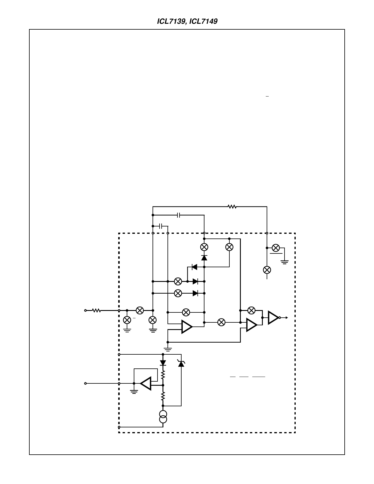
AC Voltage Measurement for ICL7139
As shown in Figure 5, the AC input voltage is applied directly
to the ICL7139 input resistor. No separate AC to DC conver-
sion circuitry is needed. The AC measurement cycle is
begun by disconnecting the integrator capacitor and using
the integrator as an autozeroed comparator to detect the
positive-going zero crossing. Once synchronized to the AC
input, the autozero loop is closed and a normal
integrate/deintegrate cycle begins. The ICL7139 resynchro-
nizes itself to the AC input prior to every reading. Because
diode D4 is in series with the integrator capacitor, only posi-
tive current from the integrator flows into the integrator
capacitor, ClNT. Since the voltage on ClNT is proportional to
the half-wave rectified average AC input voltage, a conver-
sion factor must be applied to convert the reading to RMS.
This conversion factor is π/2√2 = 1.1107, and the system
clock is manipulated to perform the RMS conversion. As a
result the deintegrate and autozero cycle times are reduced
by 10%.
AC Voltage Measurement for ICL7149
The ICL7149 is designed to be used with an optional AC to
DC voltage converter circuit. It will autorange through two
voltage ranges (400V and 40V), and the AC annunciator is
enabled. A typical averaging AC to DC converter is shown in
Figure 6, while an RMS to DC converter is shown in Figure
7. AC current can also be measured with some simple modi-
fications to either of the two circuits in Figures 6 and 7.
TRIPLE POINT
CAZ
CINT
CAZ
D1
ACS D2
RDEINT
CINT
5
ACINT
D4
DEINT
DEINT
DEINT-
VREF
~
INT V/Ω
RINTV
T
T AZ
AC IN
V+
ACINT D3
AZ
-
+
INTEGRATOR
ACS
6.7V
AZ
-
+
COMPARATOR
~
COMMON
V-
-
+
80µA
S = AZ • ACS • ACINT
T = (INT + ACS) AZ AR
ACS = AC SYNC
AR = AUTORANGE CHOPPER
AZ = AUTOZERO
INT = INTEGRATE
FIGURE 5. DETAILED CIRCUIT DIAGRAM FOR AC VOLTAGE MEASUREMENT FOR ICL7139 ONLY
3-39
Share Link: 