AS1353 데이터 시트보기 (PDF) - austriamicrosystems AG
부품명
상세내역
일치하는 목록
AS1353 Datasheet PDF : 14 Pages
| |||
AS1353/AS1356
Data Sheet - Typical Application
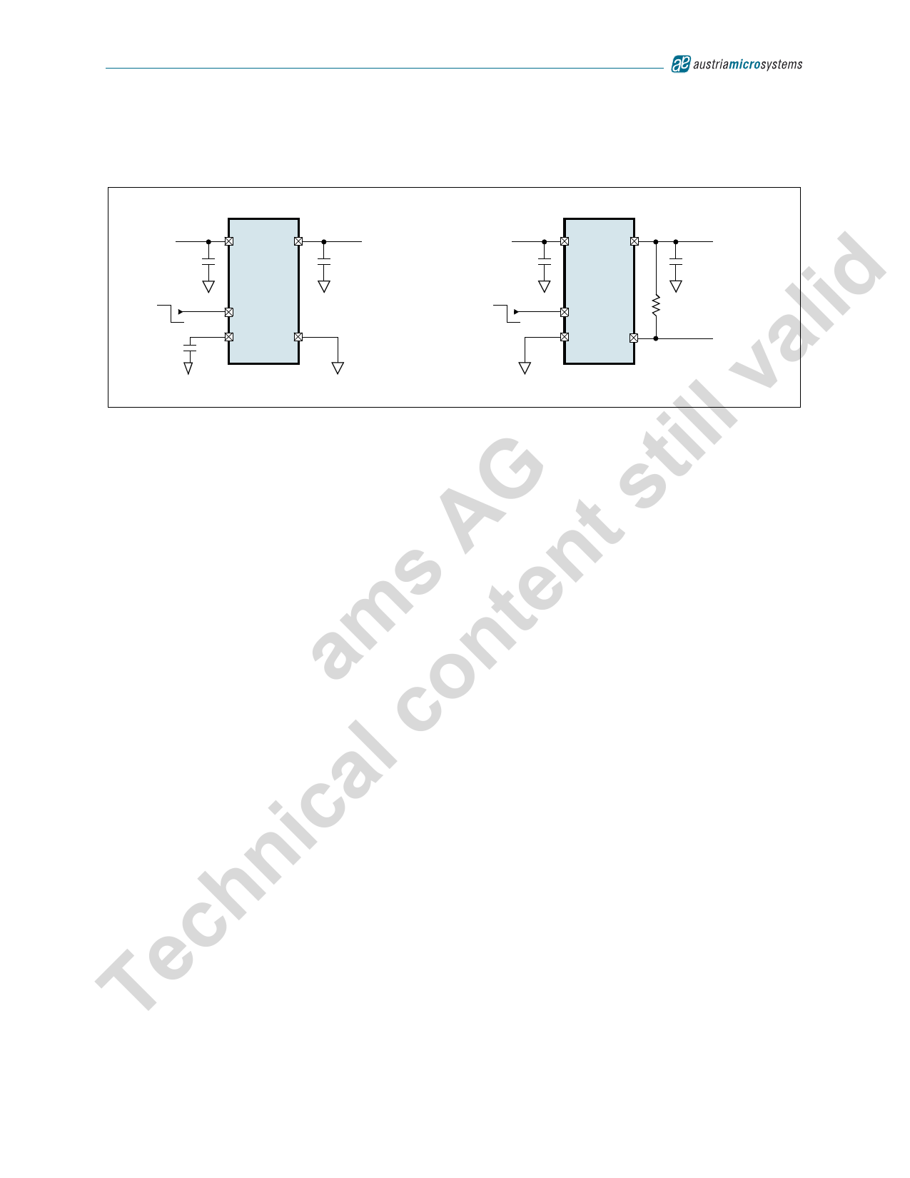
9 Typical Application
Figure 13. Typical Application Diagrams
+2.5 to
IN
OUT
Preset Output
1.5 to 3.6V,
+2.5 to
IN
OUT
Preset Output
1.5 to 3.6V,
+5.5V
CIN
1µF
AS1353
lid On
Off
CBP
0.01µF
SHDNM
BP
GND
COUT 150mA
1µF
+5.5V
CIN
1µF
On
Off
AS1356
SHDNM
GND POK
COUT 150mA
1µF
100kΩ
To Micro-
processor
ill va Capacitor Selection and Regulator Stability
Ceramic capacitors are highly recommended as they offer distinct advantages over their tantalum and aluminum elec-
t trolytic components.
For stable operation with load currents up to 150mA over the entire device temperature range, use a 1µF (min)
G s ceramic output capacitor with an ESR <0.2Ω.
Use large output capacitor values (10µF max) to reduce noise and improve load transient-response, stability and
A t power-supply rejection.
s n Note: Some ceramic capacitors exhibit large capacitance and ESR variations with variations in temperature. Z5U
and Y5V capacitors may be required to ensure stability at temperatures below TAMB = -10ºC. With X7R or X5R
e capacitors, a 1µF capacitor should be sufficient at all operating temperatures.
m t Power Supply Rejection Ratio
a n The AS1353/AS1356 are designed to deliver low dropout voltages and low quiescent currents. Power-supply rejection
is 60dB (typ) at low frequencies. To improve power supply-noise rejection and transient response, increase the values
o of the input and output bypass capacitors (see Figure 13).
The Typical Operating Characteristics (page 6) show the device line- and load-transient responses. See the Power-
c Supply Rejection Ratio vs. Frequency graph in the Typical Operating Characteristics section (page 6) for further
details.
al Dropout Voltage
For standard products with output voltage greater than the minimum VIN (2.5V), the minimum input-output voltage dif-
ic ferential (dropout voltage) determines the lowest usable supply voltage. This determines the useful end-of-life battery
voltage in battery-powered systems.
The dropout voltage is a function of the P-MOSFET drain-to-source on-resistance multiplied by the load current, and is
n calculated by:
h VDROPOUT = VIN - VOUT = RDS(ON) x IOUT
c Where:
RDS(ON) is the drain-to-source on-resistance.
e IOUT is the supply current.
TSee Typical Operating Characteristics (page 6) for further information.
(EQ 3)
www.austriamicrosystems.com
Revision 1.03
10 - 13
Share Link: 