AD7641ACP 데이터 시트보기 (PDF) - Analog Devices
부품명
상세내역
일치하는 목록
AD7641ACP Datasheet PDF : 28 Pages
| |||
AD7641
• The noise generated by the driver amplifier needs to be
kept as low as possible to preserve the SNR and transition
noise performance of the AD7641. The noise coming from
the driver is filtered by the AD7641 analog input circuit
1-pole, low-pass filter made by RIN and CIN or by the
external filter, if one is used. The SNR degradation due
to the amplifier is
⎜⎛
SNRLOSS = 20log⎜⎜
⎜⎜⎝
⎟⎞
30
⎟
900 +
πf −3dB
2
(NeN+ )2
+
πf −3dB
2
(NeN− )2
⎟
⎟⎟⎠
where:
f–3dB is the input bandwidth of the AD7641 (50 MHz) or
the cutoff frequency of the input RC filter shown in Figure 23
(3.9 MHz), if one is used.
N is the noise factor of the amplifier (1 in buffer
configuration).
eN+ and eN− are the equivalent input voltage noise densities
of the op amps connected to IN+ and IN−, in nV/√Hz.
This approximation can be used when the resistances used
around the amplifier are small. If larger resistances are
used, their noise contributions should also be root-sum
squared.
For instance, when using op amps with an equivalent input
noise density of 2.1 nV/√Hz, such as the AD8021, with a
noise gain of 1 when configured as a buffer, degrades the
SNR by only 0.25 dB when using the RC filter in Figure 23,
and by 2.5 dB without it.
• The driver needs to have a THD performance suitable to
that of the AD7641. Figure 13 gives the THD vs. frequency
that the driver should exceed.
The AD8021 meets these requirements and is appropriate for
almost all applications. The AD8021 needs a 10 pF external
compensation capacitor that should have good linearity as an
NPO ceramic or mica type. Moreover, the use of a noninverting
1 gain arrangement is recommended and helps to obtain the
best signal-to-noise ratio.
The AD8022 can also be used when a dual version is needed
and a gain of 1 is present. The AD829 is an alternative in
applications where high frequency (above 100 kHz) performance is
not required. In applications with a gain of 1, an 82 pF
compensation capacitor is required. The AD8610 is an option
when low bias current is needed in low frequency applications.
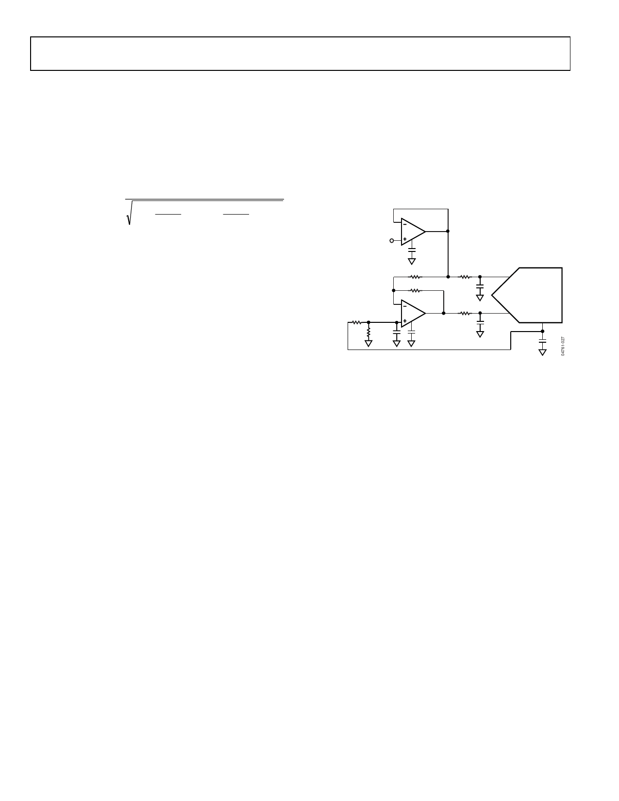
Single-to-Differential Driver
For applications using unipolar analog signals, a single-ended-
to-differential driver, as shown in Figure 26, allows for a
differential input into the part. This configuration, when
provided an input signal of 0 to VREF, produces a differential
±VREF with midscale at VREF/2. The 1-pole filter using R = 10 Ω
and C = 1 nF provides a corner frequency of 16 MHz.
If the application can tolerate more noise, the AD8139
differential driver can be used.
ANALOG INPUT
(UNIPOLAR 0V TO 2.048V)
U1
AD8021
10pF
590Ω
590Ω
15Ω
2.7nF
5kΩ
5kΩ
100nF
U2
AD8021
10pF
15Ω
2.7nF
IN+
AD7641
IN– REF
10µF
Figure 26. Single-Ended-to-Differential Driver Circuit
(Internal Reference Buffer Used)
VOLTAGE REFERENCE INPUT
The AD7641 allows the choice of either a very low temperature
drift internal voltage reference or an external reference.
Unlike many ADCs with internal references, the internal
reference of the AD7641 provides excellent performance and
can be used in almost all applications.
Internal Reference (PDBUF = Low, PDREF = Low)
To use the internal reference, the PDREF and PDBUF inputs
must both be low. This produces a 1.2 V band gap output on
REFBUFIN, which is amplified by the internal buffer and
results in a 2.048 V reference on the REF pin.
The internal reference is temperature compensated to 2.048 V ±
10 mV. The reference is trimmed to provide a typical drift of
10 ppm/°C. This typical drift characteristic is shown in Figure 7.
The output resistance of REFBUFIN is 6.33 kΩ (minimum)
when the internal reference is enabled. It is necessary to
decouple this with a ceramic capacitor greater than 100 nF.
Therefore, the capacitor provides an RC filter for noise reduction.
Because the output impedance of REFBUFIN is typically
6.33 kΩ, relative humidity (among other industrial contaminates)
can directly affect the drift characteristics of the reference.
Typically, a guard ring is used to reduce the effects of drift
under such circumstances.
Rev. 0 | Page 18 of 28
Share Link: 