A6276 데이터 시트보기 (PDF) - Allegro MicroSystems
부품명
상세내역
일치하는 목록
A6276 Datasheet PDF : 13 Pages
| |||
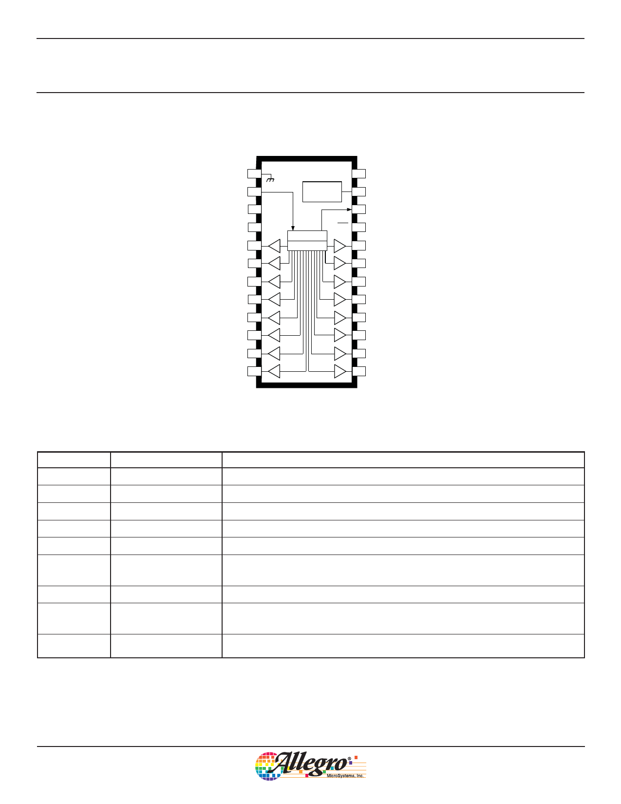
A6276
16-Bit Serial Input, Constant-Current
Latched LED Driver
Pin-out Diagram
(A, LP, and LW packages)
GROUND
SERIAL
DATA IN
CLOCK
1
2
3 CK
LATCH
ENABLE
4L
OUT 0 5
OUT 1 6
OUT 2 7
OUT 3 8
OUT 4 9
OUT 5 10
OUT 6 11
OUT 7 12
V DD
24
LOGIC
SUPPLY
IO
REGULATOR
23 R EXT
SERIAL
22 DATA OUT
REGISTER
LATCHES
OE 21 OUTPUT
ENABLE
20 OUT 15
19 OUT 14
18 OUT 13
17 OUT 12
16 OUT 11
15 OUT 10
14 OUT 9
13 OUT 8
Terminal Description
Terminal No.
1
2
3
4
5-20
21
Terminal Name
GND
SERIAL DATA IN
CLOCK
LATCH ENABLE
OUT0-15
OUTPUT ENABLE
22
SERIAL DATA OUT
23
REXT
24
SUPPLY
Function
Reference terminal for control logic.
Serial-data input to the shift-register.
Clock input terminal for data shift on rising edge.
Data strobe input terminal; serial data is latched with high-level input.
The 16 current-sinking output terminals.
When (active) low, the output drivers are enabled; when high, all output
drivers are turned OFF (blanked).
CMOS serial-data output to the following shift-register.
An external resistor at this terminal establishes the output current for all
sink drivers.
(VDD) The logic supply voltage (typically 5 V).
Allegro MicroSystems, Inc.
3
115 Northeast Cutoff
Worcester, Massachusetts 01615-0036 U.S.A.
1.508.853.5000; www.allegromicro.com
Copyright © 2000, 2003 Allegro MicroSystems, Inc.
Share Link: 