A3907 데이터 시트보기 (PDF) - Allegro MicroSystems
부품명
상세내역
일치하는 목록
A3907 Datasheet PDF : 11 Pages
| |||
A3907
Low Voltage Voice Coil Motor Driver
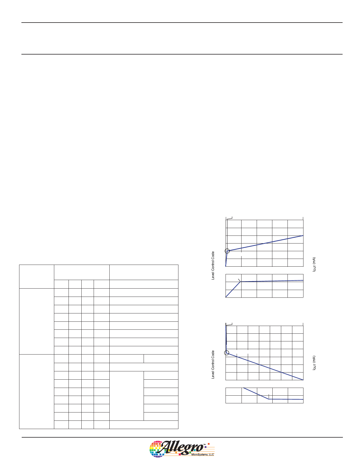
Example A
• The A3907 has been previously programmed to Level Con-
trol code 100 (11001002), for a target IOUT of 100 × 100 μA
= 10 mA (equation 1).
• The new target current level is 20 mA, so Level Control code
200 (110010002) is programmed (invert equation 1).
• For this example, the slew rate function selected is represented
by Ramp Control code 11002 : ramp, dual-subinterval, initial
subinterval delay factor 781 ns, second subinterval delay factor
50 μs.
• The A3907 determines the switchover point, T1, as follows:
CodeSwitchover = |(200 – 100)|/2 = 50 (equation 2),
T1 = 50 × 0.781 μs = 39 μs (equation 5),
IT1 = 50 + 100 × 100 μA = 150 μA (equation 6).
• The A3907 determines the target time final point, T2, as follows:
CodeSwitchover = |(200 – 100)|/2 = 50 (equation 2) ,
T2–T1 = 50 × 50 μs = 2.5 ms (equation 5).
Example B
• The A3907 has been previously programmed to Level Control
code 1000 (11111010002), for a target IOUT of 1000 × 100 μA
= 100 mA (equation 1).
Table 1. Slew Rate Function Table
Slew Rate
Method
Timer Bits Settings
T3 T2 T1 T0
0 00 0
Delay Factor
(μs)
tdT
0 (ramp feature disabled)
0 00 1
6.25
0 01 0
12.5
0 01 1
25
Single Interval
0 10 0
50
0 10 1
100
0 11 0
200
0 11 1
0 (ramp feature disabled)
T3 T2 T1 T0
1 00 0
tdT1
tdT2
0 (ramp feature disabled)
1 00 1
6.25
1 01 0
12.5
Dual Interval 1 0 1 1
25
0.781
1 10 0
50
1 10 1
100
1 11 0
200
1 11 1
0 (ramp feature disabled)
• The new target current level is 30 mA, so Level Control code
300 (1001011002) is programmed (invert equation 1).
• For this example, the slew rate function selected is represented
by Ramp Control code 11012 : ramp, dual-subinterval, initial
subinterval delay factor 781 ns, second subinterval delay factor
100 μs.
• The A3907 determines the switchover point, T2, as follows:
CodeSwitchover = |(1000 – 300)|/2 = 350 (equation 2),
T1 = 350 × 0.781 μs = 273 μs (equation 5),
IT1 = 350 + 300 × 100 μA = 65 μA (equation 6).
• The A3907 determines the target time final point, T1, as follows:
CodeSwitchover = |(1000 – 300)|/2 = 350 (equation 2) ,
T2–T1 = 350 × 100 μs = 35 ms (equation 5).
T0 T1
250
T2
25
200
20
150
15
Expanded Below
100
0
10
0.5
1.0
1.5
2.0
2.5
T1
15500
515
100
0
00..054 01.0.08
010
01..150
02.1.02 0.21.45
Time (ms)
Example A
T0 T1
1000
900
800
700
Expanded Below
600
500
400
300
0
8200
7100
5 10 15 20 25 30
T1
600
0
5 1 10 215 203 25 4 30
Time (ms)
Example B
T2
100
80
60
40
35
280
70
060
355
Figure 1. Examples of programmed IOUT change
Allegro MicroSystems, LLC
6
115 Northeast Cutoff
Worcester, Massachusetts 01615-0036 U.S.A.
1.508.853.5000; www.allegromicro.com
Share Link: 