A3906 데이터 시트보기 (PDF) - Allegro MicroSystems
부품명
상세내역
일치하는 목록
A3906 Datasheet PDF : 10 Pages
| |||
A3906
Low Voltage Stepper and Single/Dual DC Motor Driver
Parallel Operation The A3906 can be paralleled for applica-
tions that require higher output currents. In paralleled mode the
driver can source 2 A continuous. The A3906 has two completely
independent bridges with separate overcurrent latches. This
allows the device to supply two separate loads, and as a result,
when paralleled it is imperative that the internal current control is
disabled by shorting the sense pins to ground.
Because the overcurrent trip threshold is internally fixed at 0.2 V,
the trace resistance must be kept small so the internal current
latch is not triggered prematurely. With acceptable margin, the
voltage drop across the trace resistance should be under 0.1 V. At
a peak current of 2.5 A, the trace resistance should be kept below
40 mΩ to prevent false tripping of the overcurrent latch.
Each bridge has some variation in propagation delay. During this
time it is possible that one bridge will have to support the full
load current for a very short period of time. Propagation delays
are characterized and guard banded to protect the driver from
damage during these events.
Layout The printed circuit board should use a heavy ground-
plane. For optimum electrical and thermal performance, the
A3906 must be soldered directly onto the board. On the under-
side of the A3906 package is an exposed pad, which provides a
path for enhanced thermal dissipation. The thermal pad should be
soldered directly to an exposed surface on the PCB. Thermal vias
are used to transfer heat to other layers of the PCB.
Grounding In order to minimize the effects of ground bounce
and offset issues, it is important to have a low impedance single-
point ground, known as a star ground, located very close to the
device. By making the connection between the exposed thermal
pad and the ground plane directly under the A3906, that area
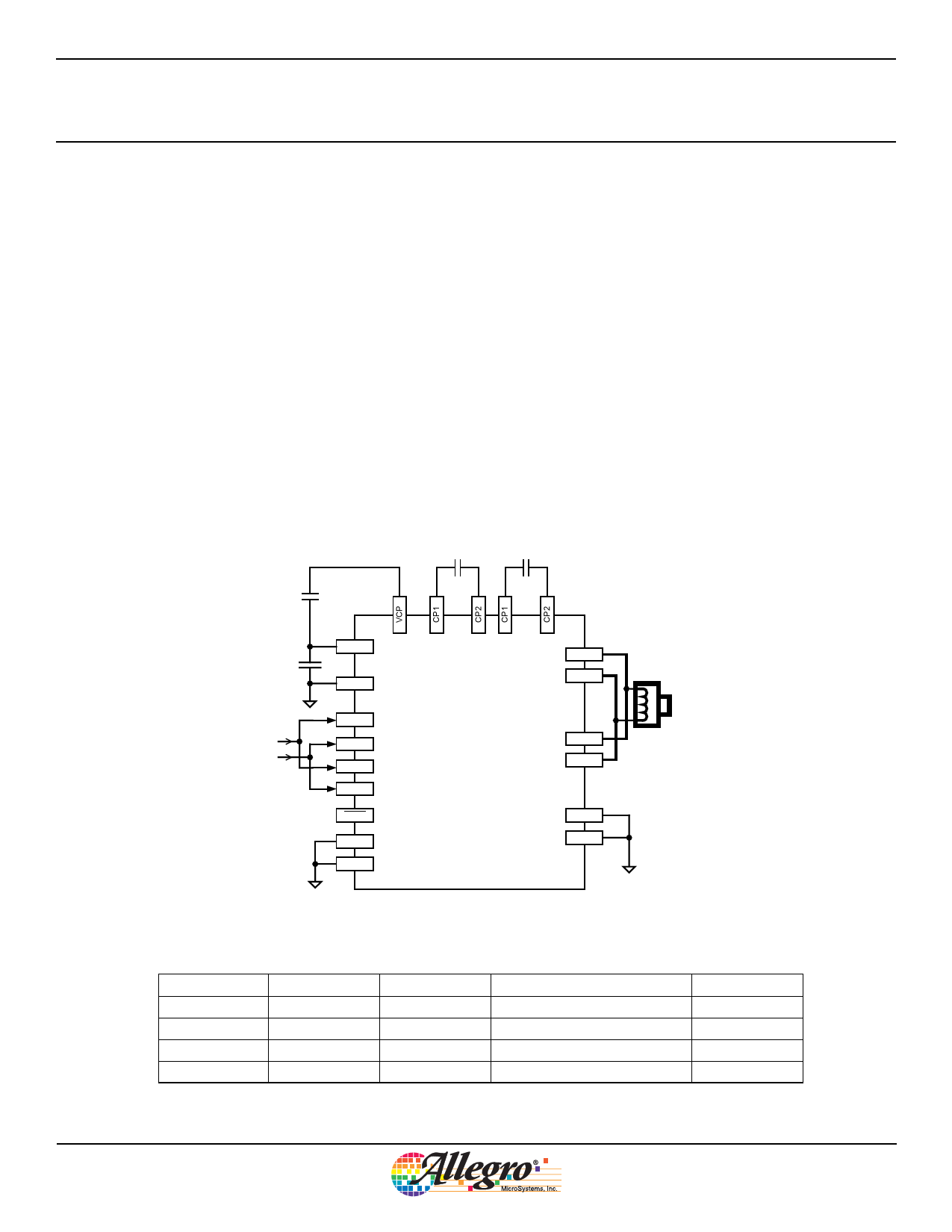
0.1 μF
10 μF
10 V
VBB
GND
IN1
IN2
IN3
IN4
SLEEP
FL1
FL2
0.1 μF
0.1 μF
A3906
OUT1A
OUT1B
OUT2A
OUT2B
SENSE1
SENSE2
DC Motor Operation (Parallel Bridge)
IN1/IN3
IN2/IN4
OUT1A/2A
0
0
OFF
1
0
H
0
1
L
1
1
L
OUT1B/2B
OFF
L
H
L
Function
Disabled
FOR
REV
BRAKE
Allegro MicroSystems, Inc.
8
115 Northeast Cutoff
Worcester, Massachusetts 01615-0036 U.S.A.
1.508.853.5000; www.allegromicro.com
Share Link: 