74HC597 데이터 시트보기 (PDF) - Philips Electronics
부품명
상세내역
일치하는 목록
74HC597 Datasheet PDF : 12 Pages
| |||
Philips Semiconductors
8-bit shift register with input flip-flops
AC WAVEFORMS
Product specification
74HC/HCT597
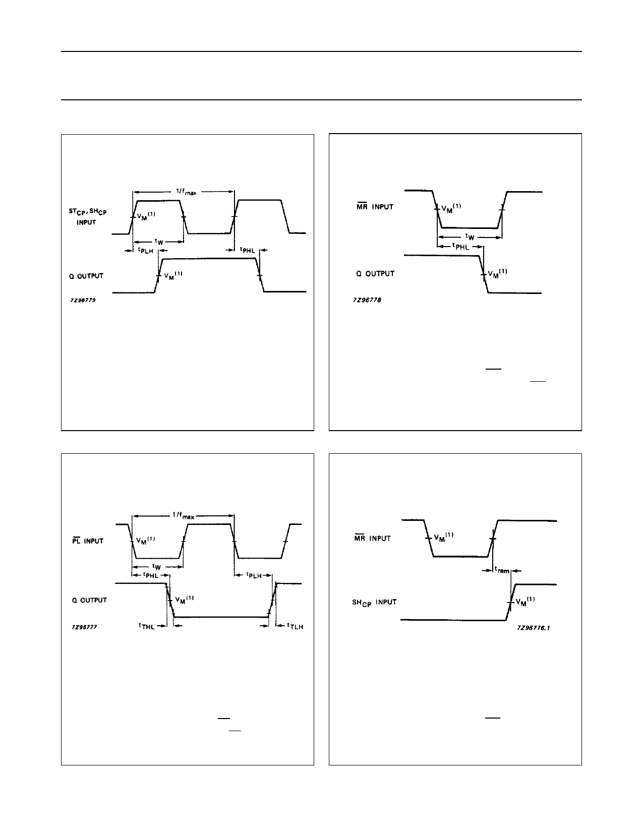
(1) HC : VM = 50%; VI = GND to VCC.
HCT : VM = 1.3 V; VI = GND to 3 V.
Fig.7
Waveforms showing the SHCP and STCP
inputs to Q output propagation delays, the
SHCP and STCP pulse widths and maximum
clock pulse frequency.
(1) HC : VM = 50%; VI = GND to VCC.
HCT : VM = 1.3 V; VI = GND to 3 V.
Fig.8 Waveforms showing the MR input to Q
output propagation delays and the MR
pulse width.
(1) HC : VM = 50%; VI = GND to VCC.
HCT : VM = 1.3 V; VI = GND to 3 V.
Fig.9 Waveforms showing the PL input to Q
output propagation delays, PL pulse width
and output transition times.
(1) HC : VM = 50%; VI = GND to VCC.
HCT : VM = 1.3 V; VI = GND to 3 V.
Fig.10 Waveforms showing the MR input to SHCP,
STCP removal times.
December 1990
11
Share Link: 