3560A-16P-CV50 데이터 시트보기 (PDF) - HIROSE ELECTRIC
부품명
상세내역
일치하는 목록
3560A-16P-CV50 Datasheet PDF : 6 Pages
| |||
The product information in this catalog is for reference only. Please request the Engineering Drawing for the most current and accurate design information.
All non-RoHS products have been discontinued, or will be discontinued soon. Please check the products status on the Hirose website RoHS search at www.hirose-connectors.com, or contact your Hirose sales representative.
B Technical DocumentⅡ
Connector Mounting Method
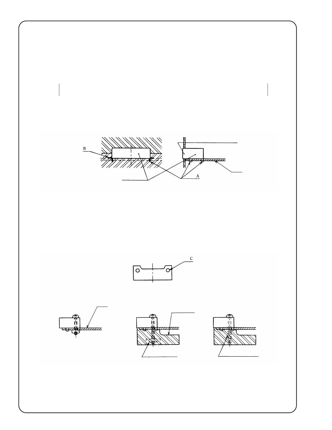
1. Soldering Method
This connector and board mounting method uses soldering at the four dip locations marked A at the left and
right sides as well as the two surface mounting locations marked B at the left and right sides for a total of six
locations.
Location A represents board through holes of 1.8mm diameter and 1mm diameter, whereas
location B represents pads of 2.8 × 1.85mm width. (See the board mounting diagram.)
As illustrated in the diagram below, the opening portion of the connector is either inserted into the body of
the set or inserted into a rectangular hole of the set.
Connector opening portion
Connector
Board
2. Soldering and Screw Fastening Method
When there is not sufficient strength with the connector opening portion at the set, the mounting holes C (as
in Figure 1) at the left and right sides of the connector are used after the solder mounting to further fix the
connector with M2 screws.
The connector can be fixed to just the board with this method (as in Figure 2); however, in consideration of
connector twisting, the most effective mounting method is to fix the connector to both the body and the
board with screws as illustrated in Figures 3 and 4.
Board
(Figure 1)
Body of the set
(Figure 2)
Nut anchoring
(Figure 3)
Tapping screw anchoring
(Figure 4)
262
04/2009
Share Link: 