33989 데이터 시트보기 (PDF) - Freescale Semiconductor
부품명
상세내역
일치하는 목록
33989 Datasheet PDF : 66 Pages
| |||
ELECTRICAL CHARACTERISTICS
STATIC ELECTRICAL CHARACTERISTICS
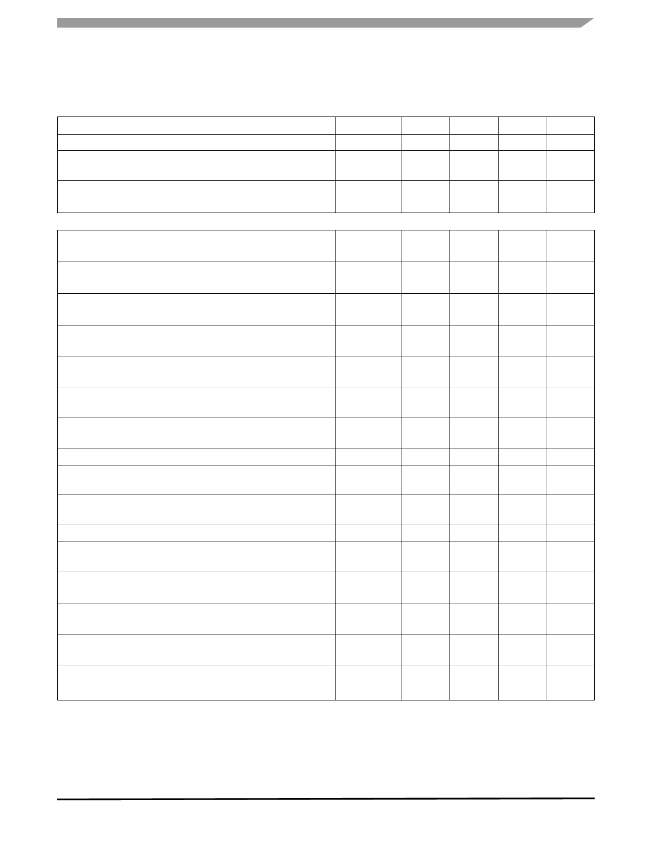
Table 3. Static Electrical Characteristics (continued)
Characteristics noted under conditions 5.5 V ≤ VSUP ≤ 18 V, -40°C ≤ TA ≤ 125°C, GND = 0 V unless otherwise noted. Typical
values noted reflect the approximate parameter means at TA = 25°C under nominal conditions unless otherwise noted.
Characteristic
Symbol
Min
Typ
Max
Unit
BATFAIL Flag Hysteresis (13)
Battery Fall Early Warning Threshold
In Normal and Standby Mode
VBF(HYS)
—
1.0
—
V
BFEW
V
5.3
5.8
6.3
Battery Fall Early Warning Hysteresis
In Normal and Standby Mode (13)
BFEWH
V
0.1
0.2
0.3
POWER OUTPUT (VDD1) (14)
VDD1 Output Voltage
VDD1OUT
V
IDD1 from 2.0 to 200 mA TAMB -40 to 125°C, 5.5 V < VSUP < 27 V
4.9
5.0
5.1
VDD1 Output Voltage
IDD1 from 2.0 to 200 mA, 4.5 V < VSUP < 5.5 V
VDD1OUT2
V
4.0
—
—
Dropout Voltage
IDD1 = 200 mA
VDD1DRP
V
—
0.2
0.5
Dropout Voltage, Limited Output Current
IDD1 = 50 mA, 4.5 V < VSUP
VDD1DRP2
V
—
0.1
0.25
IDD1 Output Current
Internally Limited
IDD1
mA
200
285
350
Junction Thermal Shutdown
Normal or Standby Modes
TSD
°C
160
—
200
Junction Over Temperature Pre-Warning
VDDTEMP Bit Set
TPW
°C
125
—
160
Temperature Threshold Difference
Reset Threshold 1
Selectable by SPI. Default Value After Reset.
TSD - TPW
20
—
40
°C
RSTTH1
V
4.5
4.6
4.7
Reset Threshold 2
Selectable by SPI
RSTTH2
V
4.1
4.2
4.3
VDD1 Range for Reset Active
Reset Delay Time
Measured at 50% of Reset Signal
VDDR
1.0
—
—
V
tD
—
µs
4.0
30
Line Regulation (C at VDD1 = 47 µF Tantal)
9.0 V VSUP < 18, IDD = 10 mA
LR1
—
mV
5.0
25
Line Regulation (C at VDD1 = 47 µF Tantal)
5.5 < VSUP < 27 V, IDD = 10 mA
LR2
—
mV
10
25
Load Regulation (C at VDD1 = 47 µF Tantal)
1.0 mA < IIDD < 200 mA
LD
mV
—
25
75
Thermal Stability
VSUP = 13.5 V, 1 = -100 mA Not Tested (15)
THERMS
mV
—
30
50
Notes
13. With CAN cell in Sleep-Disable state. If CAN cell is Sleep-Enabled for wake-up, an additional 60 µA must be added to specified value.
14. IDD1 is the total regulator output current. VDD specification with external capacitor. Stability requirement: C > 47 µF ESR < 1.3 Ω
(tantalum capacitor). In reset, normal request, normal and standby modes. Measure with C = 47 µF Tantalum.
15. Guaranteed by design; however, it is not production tested.
Analog Integrated Circuit Device Data
Freescale Semiconductor
33989
7
Share Link: 