C4501 데이터 시트보기 (PDF) - Hitachi -> Renesas Electronics
부품명
상세내역
일치하는 목록
C4501 Datasheet PDF : 5 Pages
| |||
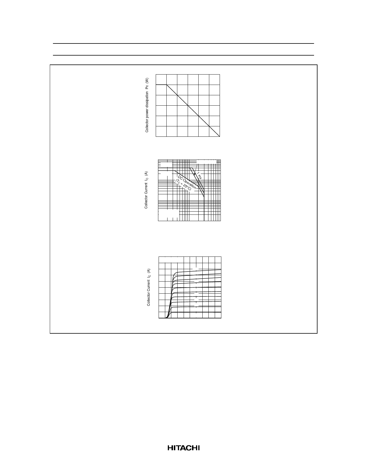
Maximum Collector Dissipation Curve
12
8
4
0
50
100
150
Case Temperature TC (°C)
Area of Safe Operation
10
iC (peak)
PW = 10 ms
3
1.0
IC (max)
(TDC
C=
O25p°eCra) tion
0.3
0.1
0.03 Ta = 25°C
1 Shot Pulse
0.01
1
3
10
30
100
Collector to emitter Voltage VCE (V)
Typical Output Characteristics
2.0
Ta = 25°C
1.6
100
90
80
1.2
70
60
50
0.8
40
30
0.4
20
10 µA
IB = 0
0
1
2
3
4
5
Collector to emitter Voltage VCE (V)
2SC4501(L)/(S)
3
Share Link: 