MXL1344ACAG 데이터 시트보기 (PDF) - Maxim Integrated
부품명
상세내역
일치하는 목록
MXL1344ACAG Datasheet PDF : 12 Pages
| |||
+5V Multiprotocol, Software-Selectable
Cable Terminator
No-Cable Mode
The MXL1344A enters no-cable mode when the mode
select inputs, M0, M1, and M2 are connected HIGH or
left unconnected. In no-cable mode, all six termination
networks are placed in V.11 mode, with S1 closed and
S2 open (Figure 4).
Applications Information
Older multiprotocol interface termination circuits have
been constructed using expensive relays with discrete
resistors, custom cables with built-in termination, or
complex circuit-board configurations to route signals to
GENERATOR
BALANCED
INTERCONNECTING
CABLE
LOAD
CABLE
TERMINATION RECEIVER
A
A′
100Ω
MIN
B
B′
C
C′
Figure 6. Typical V.11 Interface
the correct termination. The MXL1344A provides a sim-
ple solution to this termination problem. All required ter-
mination configurations are easily cable- or software-
selectable using the four mode-control input pins M0,
M1, M2, and DCE/DTE.
Using the MXL1344A in a Multiprotocol
Serial Interface
The MXL1344A terminator is designed to form a com-
plete +5V cable- or software-selectable multiprotocol
DCE/DTE interface port when used with the MXL1543
and MXL1544/MAX3175 differential driver/receivers.
The MXL1344A terminator is designed to use the VEE
power generated by the MXL1543’s charge pump and
will meet all data sheet specifications when connected
as illustrated in Figure 5. The mode-selection tables of
all three devices are identical, allowing the M0, M1, M2,
and DCE/DTE pins of each device to be connected to a
single 4-wire control bus. The MXL1543 and MXL1544/
MAX3175 provide internal pullups for the four lines,
forcing them to the logic high state if they are not
grounded. This allows interface-mode configuration by
simply strapping the appropriate pins to ground in the
interconnect cable.
In Figure 5, M1, M2 and DCE/DTE are shorted to the
cable ground, forcing logic LOW on these control lines.
Input M0 is left floating and will be pulled HIGH by
internal pullups on the MXL1543 and MXL1544/
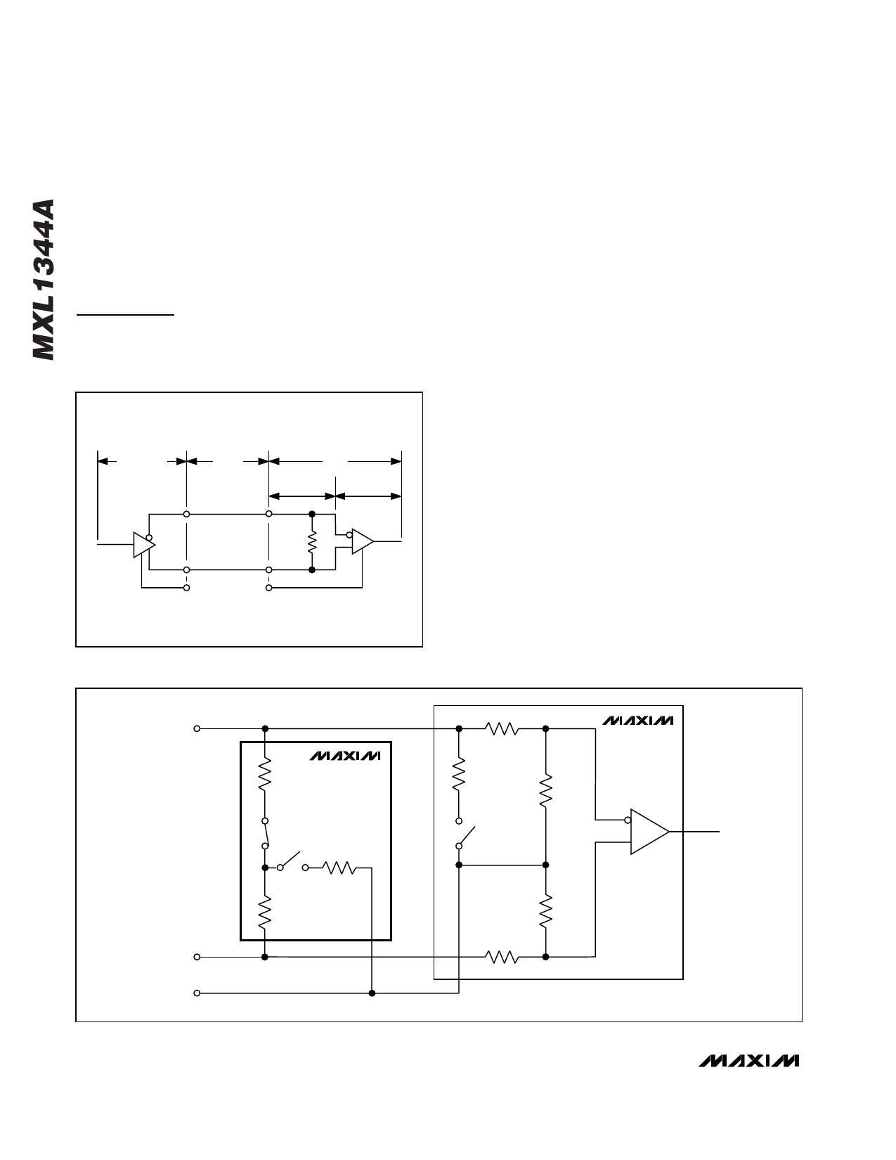
A′
R1
MXL1344A
52Ω
S1
S2
R3
127Ω
A
R5
30kΩ
R8
5kΩ
R6
10kΩ
S3
MXL1543
RECEIVER
R2
52Ω
B′
R7
10kΩ
R4
B
30kΩ
C′
GND
Figure 7. V.11 Termination and Internal Resistance Networks
8 _______________________________________________________________________________________
Share Link: 