V61188TAB 데이터 시트보기 (PDF) - EM Microelectronic - MARIN SA
부품명
상세내역
일치하는 목록
V61188TAB Datasheet PDF : 15 Pages
| |||
R
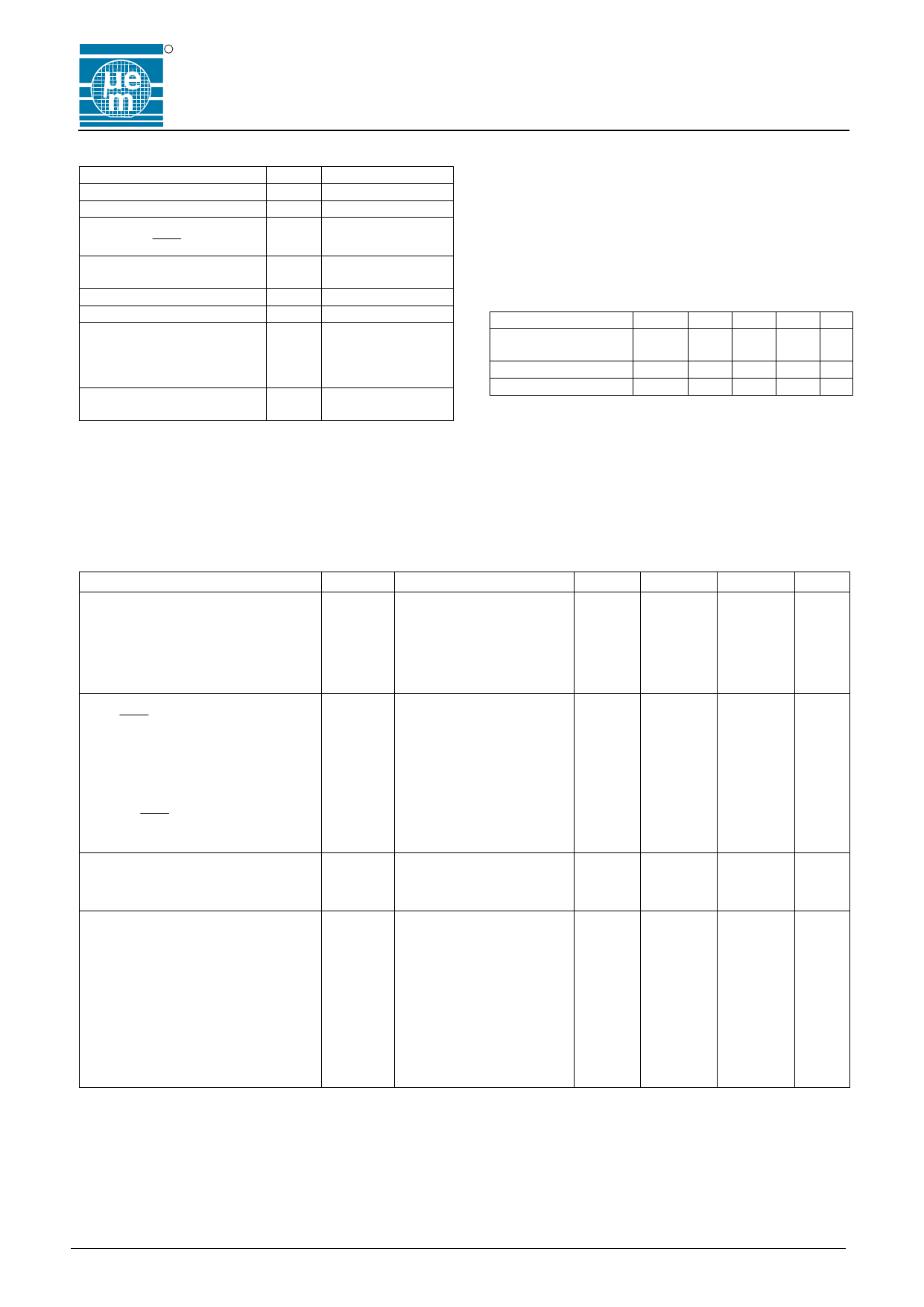
Absolute Maximum Ratings
Parameter
Symbol
Conditions
Supply voltage range
LCD supply voltage range
Voltage at DI, DO, CLK,
STR, FR, COL
VDD -0.3V to + 8V
VLCD -0.3V to + 9V
VLOGIC -0.3V to VDD+0.3V
Voltage at V1 to V3, S1 to
S40
VDISP -0.3V to VLCD + 0.3V
Storage temperature range
Power dissipation
Electrostatic discharge
TSTO -65 to +150°C
PMAX 100mW
max. to MIL-STD-883C
method 3015.7 with ref. to
VSMAX 1000V
VSS
Maximum soldering
conditions
TS 250°C x 10s
Table 1
Stresses above these listed maximum ratings may cause
permanent damages to the device. Exposure beyond
specified operating conditions may affect device
reliability or cause malfunction.
V6118
Handling Procedures
This device has built-in protection against high static
voltages or electric fields; however, anti-static
precautions must be taken as for any other CMOS
component. Unless otherwise specified, proper operation
can only occur when all terminal voltages are kept within
the voltage range. Unused inputs must always be tied to
a defined logic voltage level.
Operating Conditions
Parameter
Symbol Min Typ Max Unit
Operating
Temperature
TA -40
+85 °C
Logic supply voltage VDD
2
5
6V
LCD supply voltage VLCD 2
5
8V
Table 2
Electrical Characteristics
VDD = 5V ±10%, VLCD = 2 to 7V and TA = -40 to +85°C, unless otherwise specified
Parameter
Symbol Test Conditions
Min.
Typ.
Max. Units
Dynamic supply current
ILCD
See note 1
100
150
µA
Dynamic supply current
Dynamic supply current
IDD
See note 1 at TA = 25°C
IDD
See note 1
0.1
1
µA
3
12
µA
Dynamic supply current
IDD
See note 2
200
250
µA
Standby supply current
ISS
See note 3 at TA = 25°C
0.1
1
µA
Control Signals DI, CLK, STR, FR
and COL
Input leakage
IIN
Input capacitance
CIN
Low level input voltage
VIL
High level input voltage for DI, STR, VIH
0 < VIN < VDD
at TA = 25°C
1
8
0
2.0
100
nA
pF
0.8
V
VDD
V
FR and COL
High level input voltage for CLK
VIH
Data Output DO
3.0
VDD
V
High level output voltage
Low level output voltage
Driver Outputs S1 … S40
VOH
IH = 4 mA
VOL
IL = 4 mA
2.4
V
0.4
V
Driver impedance (note 4)
ROUT
IOUT = 10µA, VLCD = 7V
0.5
1.5
kΩ
Driver impedance (note 4)
Driver impedance (note 4)
ROUT
ROUT
IOUT = 10µA, VLCD = 3V
IOUT = 10µA, VLCD = 2V
1.2
2.5
kΩ
9
kΩ
Bias impedance V1, V2, V3 (note 5) RBIAS
IOUT = 10µA, VLCD = 7V
16
20
kΩ
Bias impedance V1, V2, V3 (note 5) RBIAS
IOUT = 10µA, VLCD = 3V
18
25
kΩ
Bias impedance V1, V2, V3 (note 5) RBIAS
IOUT = 10µA, VLCD = 2V
30
kΩ
DC output component
± VDC
see Tables 4a & 4b,
VLCD = 5V
30
50
mV
Table 3
Note 1: All outputs open, STR at VSS, FR = 400 Hz, all other inputs at VDD.
Note 2: All outputs open, STR at VSS, FR = 400 Hz, fCLK = 1 MHz, all other inputs at VDD.
Note 3: All outputs open, all other inputs at VDD.
Note 4: This is the impedance between of the voltage bias level pins (V1, V2 or V3) and the output pins S1 to S40
when a given voltage bias level is driving the outputs (S1 to S40)
Note 5: This is the impedance seen at the segment pin. Outputs measured one at a time.
Copyright © 2004, EM Microelectronic-Marin SA
2
www.emmicroelectronic.com
Share Link: 