NJU3715 데이터 시트보기 (PDF) - Japan Radio Corporation
부품명
상세내역
일치하는 목록
NJU3715 Datasheet PDF : 8 Pages
| |||
NJU357515
FUNCTIONAL DESCRIPTION
(1) Reset
When the "L" level is input to the CLR terminal, all latches are reset and all of parallel conversion
output are "L" level.
Normally, the CLR terminal should be "H" level.
(2) Data Transmission
In the STB terminal is "H" level and the clock signals are inputted to the CLK terminal, the serial data
into the DATA terminal are shifted in the shift register synchronizing at a rising edge of the clock signal.
When the STB terminal is changed to "L" level, the data in the shift register are transferred to the
latches.
Even if the STB terminal is "L" level, the input clock signal shifts the data in the shift register, therefore,
the clock signal should be controlled for data order.
Furthermore, the 4 input circuits provide a hysteresis characteristics using the schmitt trigger structure
to protect the noise.
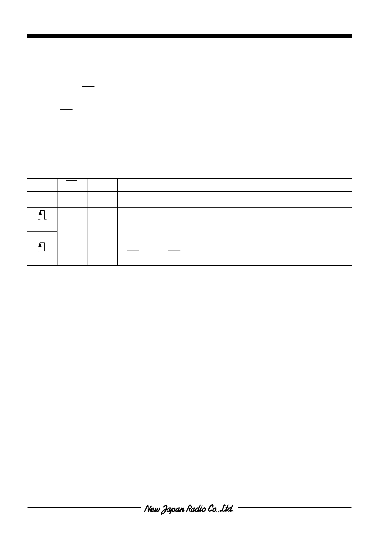
CLK
STB
CLR
X
X
L
H
H
L
H
L
H
Note 1) X: Don’t care
OPERATION
All of latches are reset (the data in the shift register is no change).
All of parallel conversion outputs are "L".
The serial data into the DATA terminal are inputted to the shift register.
In this stage, the data in the latch is not changed.
The data in the shift register is transferred to the latch. And the data in the
latch is output from the parallel conversion output terminals.
When the clock signal is inputted into the CLK terminal in state of the
STB="L" and CLR="H", the data is shifted in the shift register and latched
data is also changed in accordance with the shift register.
Ver.2003-11-18
-3-
Share Link: 