R331-05 데이터 시트보기 (PDF) - Hamamatsu Photonics
부품명
상세내역
일치하는 목록
R331-05 Datasheet PDF : 2 Pages
| |||
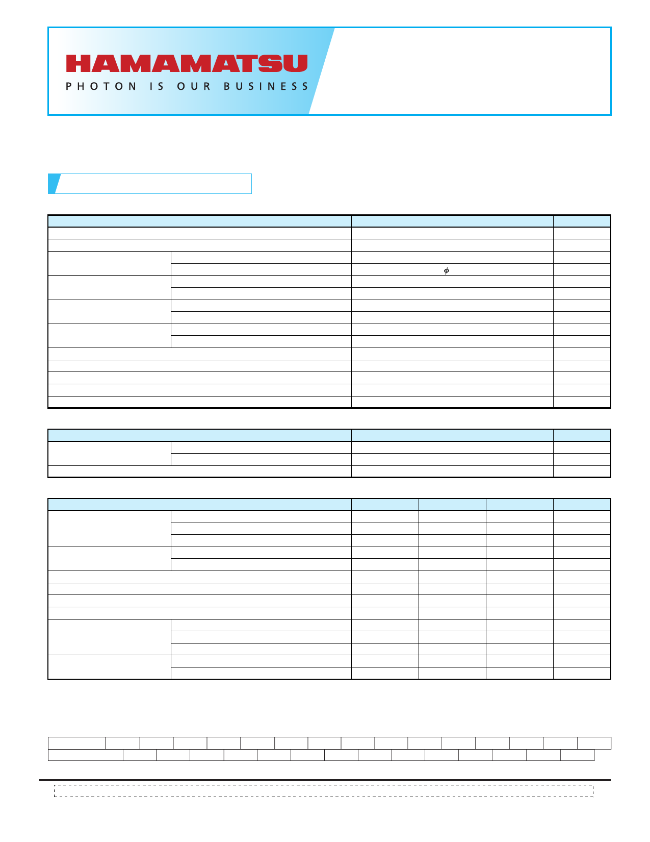
PHOTOMULTIPLIER TUBE
R331-05
For Liquid Scintillation Counting, Photon Counting Application
51mm (2 Inch) Diameter, Bialkali Photocathode, 12 Stages, Head-On Type
SPECIFICATIONS
GENERAL
Parameter
Spectral Response
Wavelength of Maximum Response
Photocathode
MateriaI
Minimum Effective Area
Window Material
Material
Shape
Dynode
Structure
Number of Stages
Direct Interelectrode
Anode to Last Dynode
Capacitances
Anode to All Other Electrodes
Base
SuitabIe Socket
Weight
Operation Ambient Temperature
Storage Temperature
Description / Value
Unit
300 to 650
nm
420
nm
Bialkali
—
46
mm
Low K content borosilicate glass (Frosted)
—
Concave-Convex
—
Linear focused
—
12
—
2
pF
2.5
pF
21-pin glass base
—
E678-21C (supplied)
—
150
g
-30 to +50
°C
-80 to +50
°C
MAXIMUM RATINGS (Absolute Maximum Values)
Parameter
Value
Unit
Supply Voltage
Between Anode and Cathode
Between Anode and Last Dynode
2500
V
500
V
Average Anode Current
0.2
mA
CHARACTERISTICS (at 25 °C)
Cathode Sensitivity
Parameter
Luminous (2856K)
Blue Index (CS 5-58 filter)
Min.
60
9.0
Typ.
90
10.5
Max.
—
—
Unit
µA/lm
—
Quantum Efficiency at Peak Wavelength
—
Anode Sensitivity
Luminous (2856K)
Radiant at Peak Wavelength
30
—
Gain
—
Anode Dark Current (after 30 min storage in darkness)
—
Dark Counts
—
Background Noise*
—
Anode Pulse Rise Time
—
25
120
1.1 × 10⁵
1.3 × 10⁶
10
1000
18
2.6
—
—
—
—
50
2000
27
—
%
A/lm
A/W
—
nA
s-1
m-1
ns
Time Response
Electron Transit Time
—
48
—
ns
Transit Time Spread (FWHM)
—
1.1
—
ns
Pulse Linearity
2 % Deviation
5 % Deviation
—
15
—
mA
—
30
—
mA
* Background noise is the noise count measured as a pair at Hamamatsu Photonics K.K. with coincident resolving time (τ) of 25 ns.
It includes noise counts by natural radiation and chance coincident counts per minute is calculated by (2 × N1 × N2 × τ) × 60 where N1 and N2 are
dark counts per second of each PMT used as a pair.
VOLTAGE DlSTRlBUTlON RATlO AND SUPPLY VOLTAGE
Electrodes K
G Dy1 Dy2 Dy3 Dy4 Dy5 Dy6 Dy7 Dy8 Dy9 Dy10 Dy11 Dy12 P
Ratio
4
0
1 1.4 1
1
1
1
1
1
1
1
1
1
SuppIy Voltage: 1500 V, K: Cathode, Dy: Dynode, P: Anode, G: Grid * Shield should be connected to Dy5
Subject to local technical requirements and regulations, availability of products included in this promotional material may vary. Please consult with our sales office.
Information furnished by HAMAMATSU is believed to be reliable. However, no responsibility is assumed for possible inaccuracies or omissions. Specifications are
subject to change without notice. No patent rights are granted to any of the circuits described herein. ©2014 Hamamatsu Photonics K.K.
Share Link: 