PS11011 데이터 시트보기 (PDF) - Powerex
부품명
상세내역
일치하는 목록
PS11011 Datasheet PDF : 6 Pages
| |||
MITSUBISHI SEMICONDUCTOR <Application Specific Intelligent Power Module>
PS11011
FLAT-BASE TYPE
INSULATED TYPE
TOTAL SYSTEM
Symbol
Item
Condition
Ratings
Unit
Tj
Junction temperature
(Note 2)
–20 ~ +125
°C
Tstg
Storage temperature
—
–40 ~ +125
°C
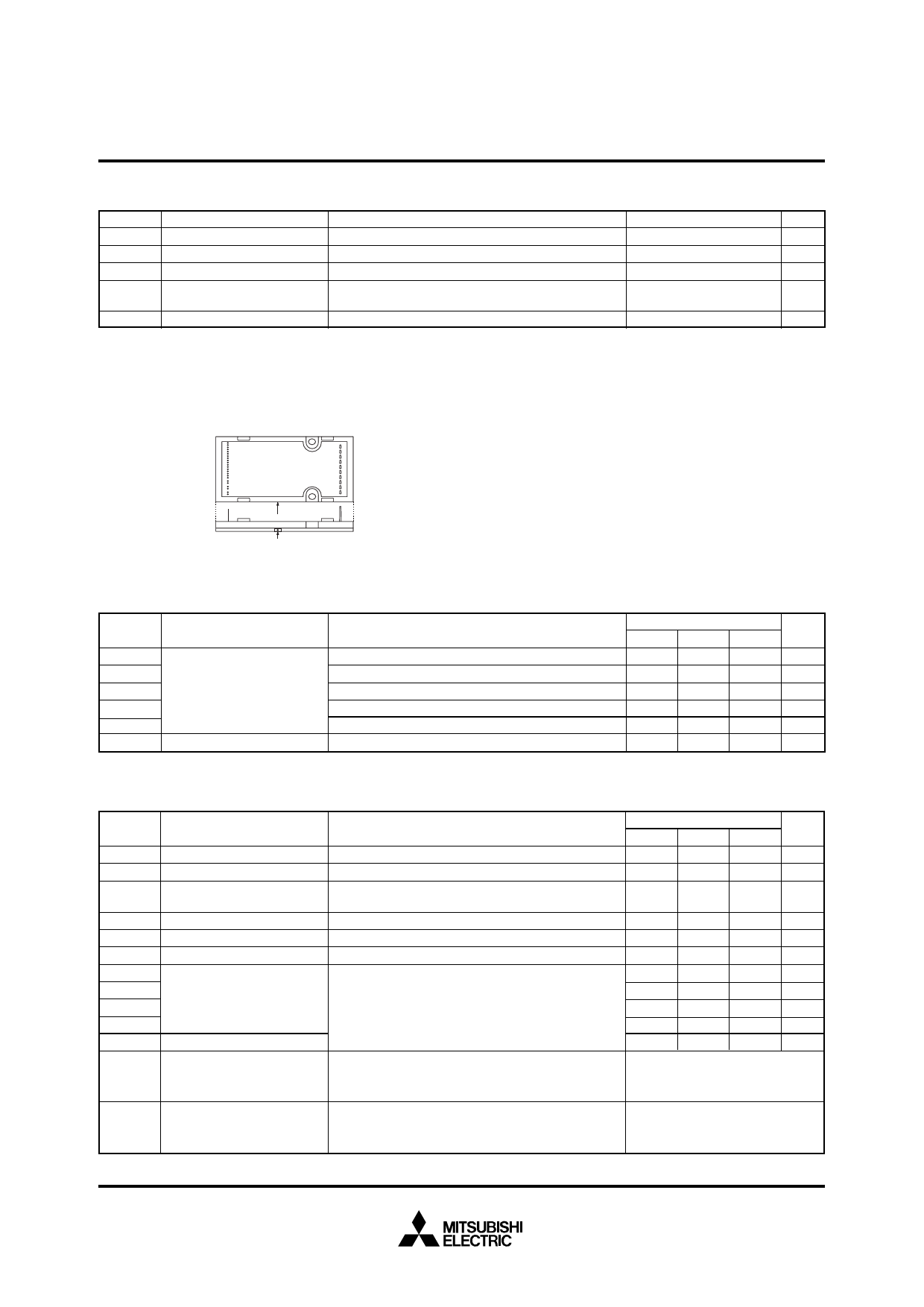
TC
Module case operating temperature
(Fig. 3)
–20 ~ +100
°C
Viso
Isolation voltage
60 Hz sinusoidal AC applied between all terminals and
the base plate for 1 minute.
2500
Vrms
—
Mounting torque
Mounting screw: M3.5
0.78 ~ 1.27
kg·cm
Note 2) The item defines the maximum junction temperature for the power elements (IGBT/Diode) of the ASIPM to ensure safe operation. How-
ever, these power elements can endure junction temperature as high as 150°C instantaneously . To make use of this additional tem-
perature allowance, a detailed study of the exact application conditions is required and, accordingly, necessary information is requested
to be provided before use.
CASE TEMPERATURE MEASUREMENT POINT (3mm from the base surface)
TC
(Fig. 3)
THERMAL RESISTANCE
Symbol
Item
Rth(j-c)Q
Rth(j-c)F
Rth(j-c)QB
Rth(j-c)FB
Rth(j-c)FR
Rth(c-f)
Junction to case Thermal
Resistance
Contact Thermal Resistance
Condition
Inverter IGBT (1/6)
Inverter FWDi (1/6)
Brake IGBT
Brake FWDi
Converter Di (1/6)
Case to fin, thermal grease applied (1 Module)
Ratings
Min.
Typ.
Max. Unit
—
—
7.3 °C/W
—
—
6.1 °C/W
—
—
7.3 °C/W
—
—
6.1 °C/W
—
—
4.8 °C/W
—
—
0.053 °C/W
ELECTRICAL CHARACTERISTICS (Tj = 25°C, VDH = 15V, VDB = 15V unless otherwise noted)
Symbol
Item
Condition
VCE(sat)
VEC
VCE(sat)Br
VFBr
IRRM
VFR
ton
tc(on)
toff
tc(off)
trr
Collector-emitter saturation voltage VDH = VDB = 15V, Input = ON, Tj = 25°C, IC = 2A
FWDi forward voltage
Tj = 25°C, IC = –2A, Input = OFF
Brake IGBT
Collector-emitter saturation voltage
VDH = 15V, Input = ON, Tj = 25°C, IC = 2A
Brake diode forward voltage Tj = 25°C, IF = 2A, Input = OFF
Converter diode reverse current VR = VRRM, Tj = 125°C
Converter diode voltage
Tj = 25°C, IF = 5A
1/2 Bridge inductive load, Input = ON
Switching times
VCC = 300V, Ic = 2A, Tj = 125°C
VDH = 15V, VDB = 15V
FWD reverse recovery time
Note : ton, toff include delay time of the internal control
circuit
Short circuit endurance
VCC ≤ 400V, Input = ON (one-shot)
(Output, Arm, and Load,
Tj = 125°C start
Short Circuit Modes)
13.5V ≤ VDH = VDB ≤ 16.5V
VCC ≤ 400V, Tj ≤ 125°C,
Switching SOA
Ic < IOL(CL) operation level, Input = ON
13.5V ≤ VDH = VDB ≤ 16.5V
Ratings
Unit
Min.
Typ.
Max.
—
—
2.9
V
—
—
2.9
V
—
—
3.5
V
—
—
2.9
V
—
—
8
mA
—
—
1.5
V
0.3
0.6
1.5
µs
—
0.2
0.6
µs
—
1.1
1.8
µs
—
0.35
1.0
µs
—
0.1
—
µs
• No destruction
• FO output by protection operation
• No destruction
• No protecting operation
• No FO output
Jan. 2000
Share Link: 