MAX8743(2004) 데이터 시트보기 (PDF) - Maxim Integrated
부품명
상세내역
일치하는 목록
MAX8743
(Rev.:2004)
(Rev.:2004)
Maxim Integrated

MAX8743 Datasheet PDF : 27 Pages
| |||
Dual, High-Efficiency, Step-Down
Controller with High Impedance in Shutdown
shot is triggered if the error comparator is low, the low-
side switch current is below the current-limit threshold,
and the minimum off-time one-shot has timed out
(Table 3).
On-Time One-Shot (TON)
The heart of the PWM core is the one-shot that sets the
high-side switch on-time for both controllers. This fast,
low-jitter, adjustable one-shot includes circuitry that
varies the on-time in response to battery and output
voltage. The high-side switch on-time is inversely pro-
portional to the battery voltage as measured by the V+
input, and proportional to the output voltage. This algo-
rithm results in a nearly constant switching frequency
despite the lack of a fixed-frequency clock generator.
The benefits of a constant switching frequency are
twofold: First, the frequency can be selected to avoid
noise-sensitive regions such as the 455kHz IF band;
second, the inductor ripple-current operating point
remains relatively constant, resulting in easy design
methodology and predictable output voltage ripple.
The on-times for side 1 are set 35% higher than the on-
times for side 2. This is done to prevent audio-frequen-
cy “beating” between the two sides, which switch asyn-
chronously for each side. The on-time is given by:
On-time = K (VOUT + 0.075V) / VIN
where K is set by the TON pin-strap connection (Table
4), and 0.075V is an approximation to accommodate
for the expected drop across the low-side MOSFET
switch. One-shot timing error increases for the shorter
on-time settings due to fixed propagation delays; it is
approximately ±12.5% at higher frequencies and ±10%
at lower frequencies. This translates to reduced switch-
ing-frequency accuracy at higher frequencies (Table
4). Switching frequency increases as a function of load
current due to the increasing drop across the low-side
MOSFET, which causes a faster inductor-current dis-
charge ramp. The on-times guaranteed in the Electrical
Characteristics tables are influenced by switching
delays in the external high-side power MOSFET.
Two external factors that influence switching-frequency
accuracy are resistive drops in the two conduction
VDD = 5V
BIAS SUPPLY
C9
4.7µF
C8
1µF
R3
20Ω
C11
1µF
C1
3 ✕ 10µF
OUTPUT1
L1
Q1
1.8V, 8A 2.2µH
C3
3 ✕ 470µF
D1 Q2
C5
0.1µF
R1
C7
5mΩ
0.22µF
D3
CMPSH-3A
4
21
9
22
VDD
UVP
VCC
V+
ON1 11
3 ILIM1
13 ILIM2
ON2 12
OVP 8
MAX8743EEI
25
BST1
BST2 19
26
DH1
18
DH2
27
LX1
24
DL1
5 TON
28 CS1
1 OUT1
10
REF
2 FB1
23 GND
LX2 17
DL2 20
CS2 16
OUT2 15
SKIP 6
14
FB2
7
PGOOD
Q3
C6
0.1µF
Q4
5V
100kΩ
VIN
7V TO 24V
ON/OFF
CONTROLS
C2
2 ✕ 10µF
L2
4.7µH
D2
OUTPUT2
2.5V, 4A
C4
470µF
R2
10mΩ
POWER-GOOD
INDICATOR
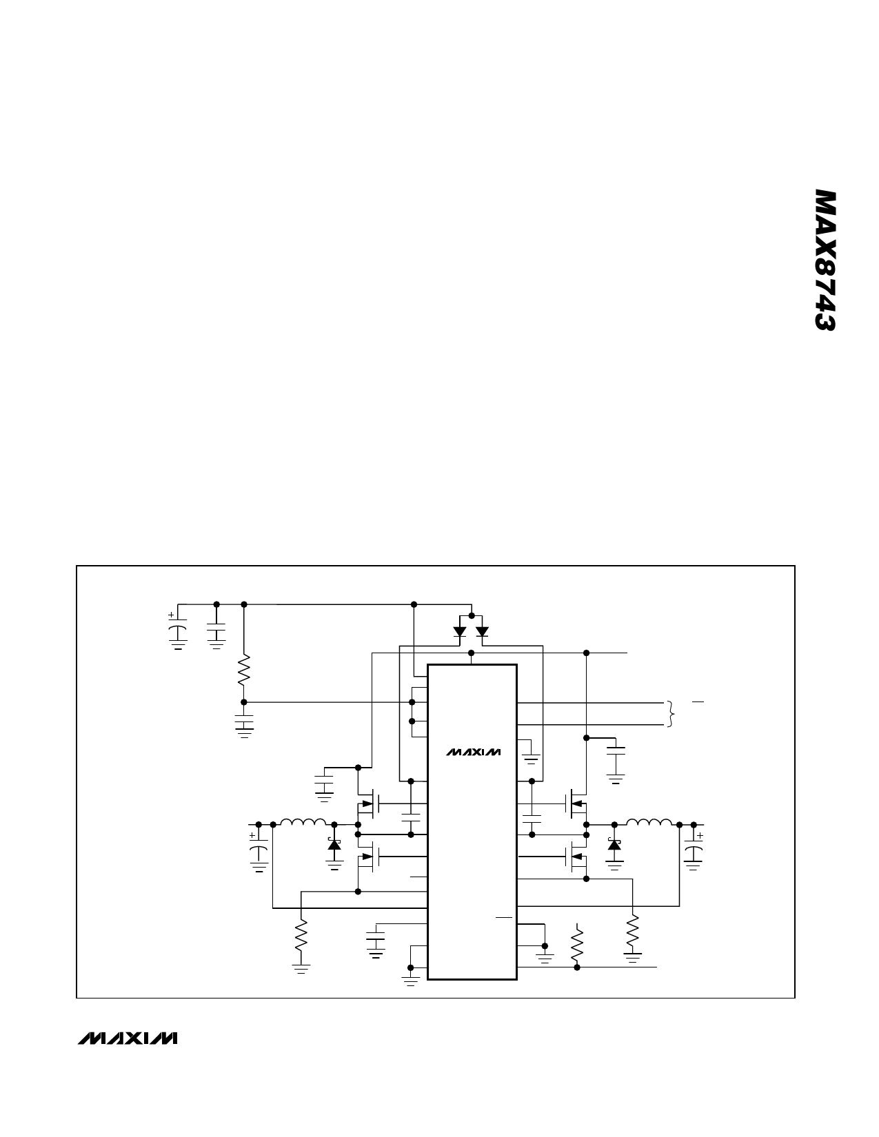
Figure 1. Standard Application Circuit
______________________________________________________________________________________ 11
Share Link: