MAX8740 데이터 시트보기 (PDF) - Maxim Integrated
부품명
상세내역
일치하는 목록
MAX8740 Datasheet PDF : 12 Pages
| |||
TFT-LCD Step-Up DC-DC Converter
Soft-Start
The MAX8740 can be programmed for soft-start upon
power-up with an external capacitor. When the shutdown
pin is taken high, the soft-start capacitor (CSS) is immedi-
ately charged to 0.4V. Then the capacitor is charged at a
constant current of 4.5µA (typ). During this time, the SS
voltage directly controls the peak inductor current, allow-
ing 0A at VSS = 0.4V to the full current limit at VSS = 1.5V.
The maximum load current is available after the soft-start
is completed. When the SHDN pin is taken low, the soft-
start capacitor is discharged to ground.
Frequency Selection
The MAX8740’s frequency can be user selected to oper-
ate at either 640kHz or 1.2MHz. Connect FREQ to GND
for 640kHz operation. For a 1.2MHz switching frequency,
connect FREQ to IN. This allows the use of small, mini-
mum-height external components while maintaining low
output noise. FREQ has an internal pulldown, allowing
the user the option of leaving FREQ unconnected for
640kHz operation.
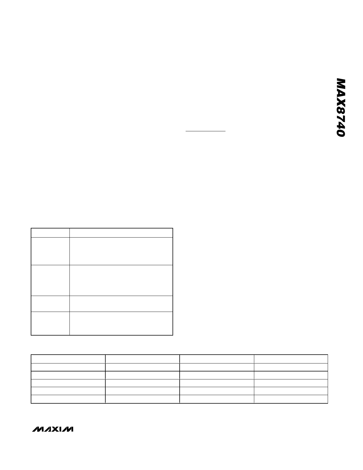
Table 1. Component List
DESIGNATION
DESCRIPTION
10µF ±10%, 6.3V X5R ceramic capacitor
C1
(0805)
Murata GRM21BR60J106K
Taiyo Yuden JMK212BJ106KD
C2, C7
10µF ±20%, 25V X5R ceramic capacitors
(1210)
TDK C3225X5R1E106M,
Taiyo Yuden TMK325BJ106MM
D1
3A, 40V Schottky diode (SM8)
Central Semiconductor CMSH3-40M
3.3µH ±30%, 4.0A power inductor
L1
Sumida CDRH8D28-3R3, 3.3µH
(alternate : Sumida CDRH103R-3R3, 3.3µH)
Table 2. Component Suppliers
SUPPLIER
Murata
Sumida
Taiyo Yuden
TDK
Toshiba
PHONE
770-436-1300
847-545-6700
800-348-2496
847-803-6100
949-455-2000
Shutdown
The MAX8740 shuts down to reduce the supply current
to 0.1µA when SHDN is low. In this mode, the internal
reference, error amplifier, comparators, and biasing cir-
cuitry turn off, and the n-channel MOSFET is turned off.
The step-up regulator’s output is connected to IN by
the external inductor and rectifier diode.
Applications Information
Step-up regulators using the MAX8740 can be designed
by performing simple calculations for a first iteration. All
designs should be prototyped and tested prior to pro-
duction. Table 1 provides a list of power components for
the typical applications circuit. Table 2 lists component
suppliers.
External-component-value choice is primarily dictated
by the output voltage and the maximum load current,
as well as maximum and minimum input voltages.
Begin by selecting an inductor value. Once L is known,
choose the diode and capacitors.
Inductor Selection
The minimum inductance value, peak current rating, and
series resistance are factors to consider when selecting
the inductor. These factors influence the converter’s effi-
ciency, maximum output load capability, transient-
response time, and output voltage ripple. Physical size
and cost are also important factors to be considered.
The maximum output current, input voltage, output volt-
age, and switching frequency determine the inductor
value. Very high inductance values minimize the cur-
rent ripple and therefore reduce the peak current,
which decreases core losses in the inductor and I2R
losses in the entire power path. However, large induc-
tor values also require more energy storage and more
turns of wire, which increase physical size and can
increase I2R losses in the inductor. Low inductance val-
ues decrease the physical size but increase the current
ripple and peak current. Finding the best inductor
involves choosing the best compromise between circuit
efficiency, inductor size, and cost.
FAX
770-436-3030
847-545-6720
847-925-0899
847-390-4405
949-859-3963
WEBSITE
www.murata.com
www.sumida.com
www.t-yuden.com
www.component.tdk.com
www.toshiba.com/taec
_______________________________________________________________________________________ 7
Share Link: 