PS21204 데이터 시트보기 (PDF) - MITSUBISHI ELECTRIC
부품명
상세내역
일치하는 목록
PS21204 Datasheet PDF : 8 Pages
| |||
MITSUBISHI SEMICONDUCTOR <Dual-In-Line Package Intelligent Power Module>
PS21204
TRANSFER-MOLD TYPE
INSULATED TYPE
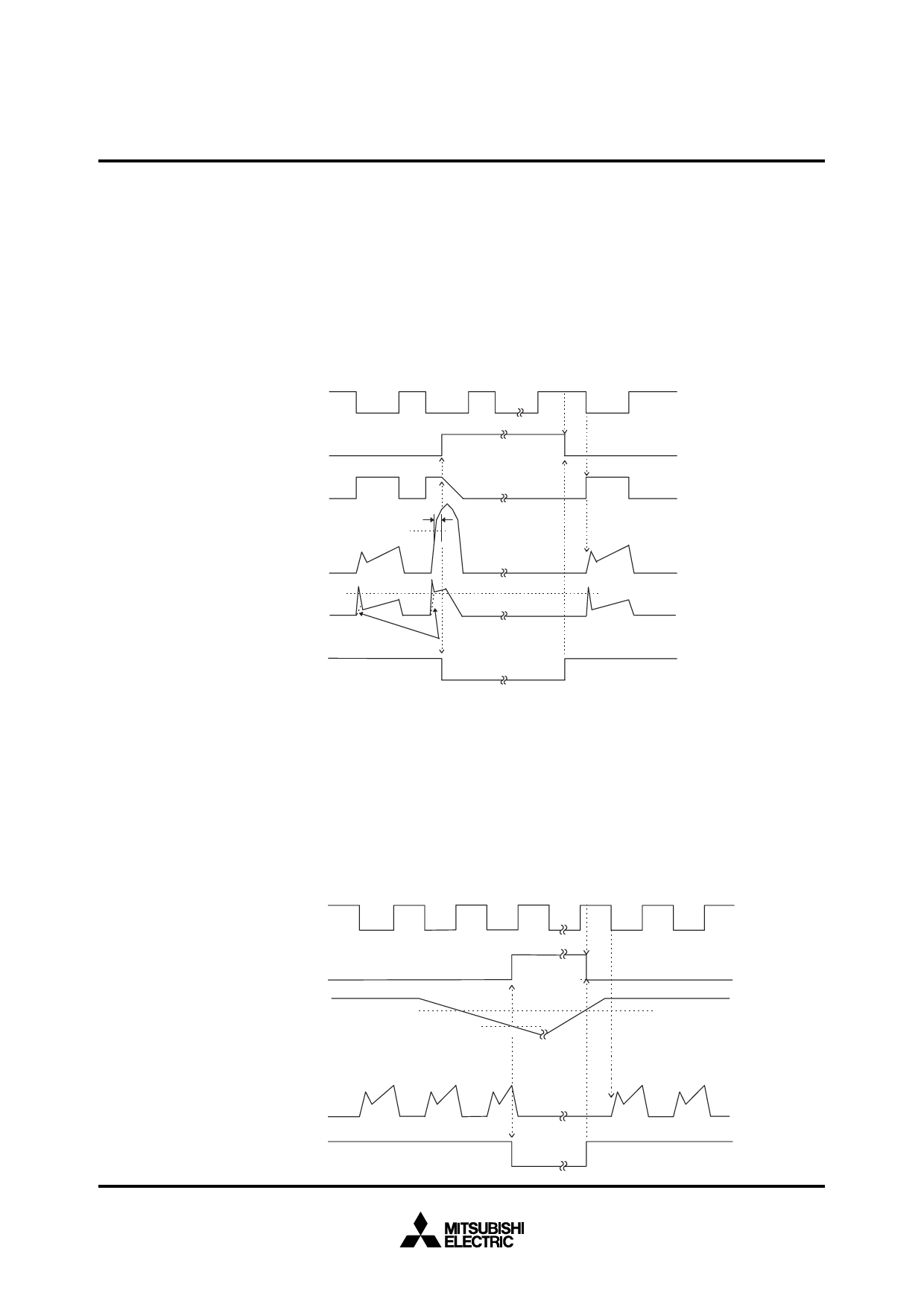
Fig. 5 TIMING CHARTS OF THE DIP-IPM PROTECTIVE FUNCTIONS
[A] Short-Circuit Protection (Lower-arms only)
(For the external shunt resistance and CR connection, please refer to Fig. 3.)
a1. Normal operation : IGBT ON and carrying current.
a2. Short circuit current detection (SC trigger).
a3. Hard IGBT gate interrupt.
a4. IGBT turns OFF.
a5. FO timer operation starts : The pulse width of the FO signal is set by the external capacitor CFO.
a6. Input “H” : IGBT OFF state.
a7. Input “L” : IGBT ON state, but during the FO active signal the IGBT doesn’t turn ON.
a8. IGBT OFF state.
Lower-arms control input
Protection circuit state
a6 a7
SET
RESET
Internal IGBT gate
Output current Ic(A)
Sense voltage of the
shunt resistance
Error output Fo
a3
a2
SC
a1
a4
a8
SC reference voltage
CR circuit time constant DELAY (*Note)
a5
Note : The CR time constant safe guards against erroneous SC fault signals resulting from di/dt generated voltages when the IGBT turns ON.
The optimum setting for the CR circuit time constant is 1.5~2.0µs.
[B] Under-Voltage Protection (N-side, UVD)
a1. Normal operation : IGBT ON and carrying current.
a2. Under voltage trip (UVDt).
a3. IGBT OFF inspite of control input condition.
a4. FO timer operation starts : The pulse width of the FO signal is set by the external capacitor CFO.
a5. Under voltage reset (UVDr).
a6. Normal operation : IGBT ON and carrying current.
Control input
Protection circuit state
Control supply voltage VD
UVDr
SET
RESET
UVDt a2
a5
a1
a3
a6
Output current Ic(A)
Error output Fo (N-side only)
a4
Aug. 1999
Share Link: 