EM4006F9WW7 데이터 시트보기 (PDF) - EM Microelectronic - MARIN SA
부품명
상세내역
일치하는 목록
EM4006F9WW7
EM Microelectronic - MARIN SA

EM4006F9WW7 Datasheet PDF : 10 Pages
| |||
Modulator Switch
Due to the low impedance of the antenna and resonant
capacitor the Modulator Switch has to present low RF
impedance when switched ON (about 100 ohms).
The minimum time period with the Modulator Switch ON
is 38 µs. At lower data rates this time is even much
longer. The current consumption of divider chain running
at 13 MHz is near 60 µA. Putting together this two figures
it is clear that it is not possible to supply the IC during the
time the Modulator Switch is ON from the integrated
Supply Buffer Capacitor which value is approximately 140
pF. The IC has to get power from the RF field also during
the time the Modulator Switch is ON.
EM4006
This problem is solved by putting the Modulator Switch on
the output of the Rectifier (between VDD and VSS) and
regulating its ON resistance in function of supply voltage.
When the supply voltage is high the ON impedance is low.
When the supply voltage drops near the region where the
operation of the IC at 13.56 MHz is not guaranteed the
ON impedance is increased in order to prevent further
drop.
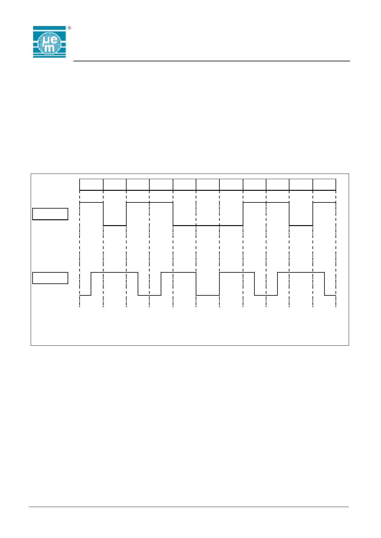
NRZ-L
STREAM
10 11 000 11 01
DM-M
CODED
Bit i-1 Bit i
x
1
0
0
1
0
no transition at the beginning of Bit i,
transition at the beginning of Bit i,
no transition at the beginning of Bit i,
transition in the middle of Bit i
no transition in the middle of Bit i
no transition in the middle of Bit i
Power Supply Management
For a correct operation, the device must be initialised.
When the transponder is put in the RF field, the supply
voltage increases until it achieves Vr limit (see Figure 7).
During this time and for an additionnal 64 bit period, the
modulator switch is on and the device initialises its
internal logic.
Fig. 6
At this point, the data transmission starts and runs while
the supply voltage is higher than Vmin. If the supply
voltage decreases under this limit, the device is again in
an initialising state and the modulator is on.
Copyright 2001, EM Microelectronic-Marin SA
6
www.emmicroelectronic.com
Share Link: