EM4006F9WP11 데이터 시트보기 (PDF) - EM Microelectronic - MARIN SA
부품명
상세내역
일치하는 목록
EM4006F9WP11
EM Microelectronic - MARIN SA

EM4006F9WP11 Datasheet PDF : 10 Pages
| |||
Absolute Maximum Ratings
Parameter
Maximum DC Current forced
on COIL1 and COIL2
Power Supply
Storage Temp. Die form
Storage Temp. PCB form
Electrostatic discharge
maximum to MIL-STD-883C
method 3015
Symbol
ICMAX
VDD
Tst
Tst
VESD
Conditions
±30mA
-0.3V to 7.5V
-55 to +200°C
-55 to +125°C
2000V
Stresses above these listed maximum ratings may cause
permanent damages to the device. Exposure beyond
specified operating conditions may affect device reliability
or cause malfunction.
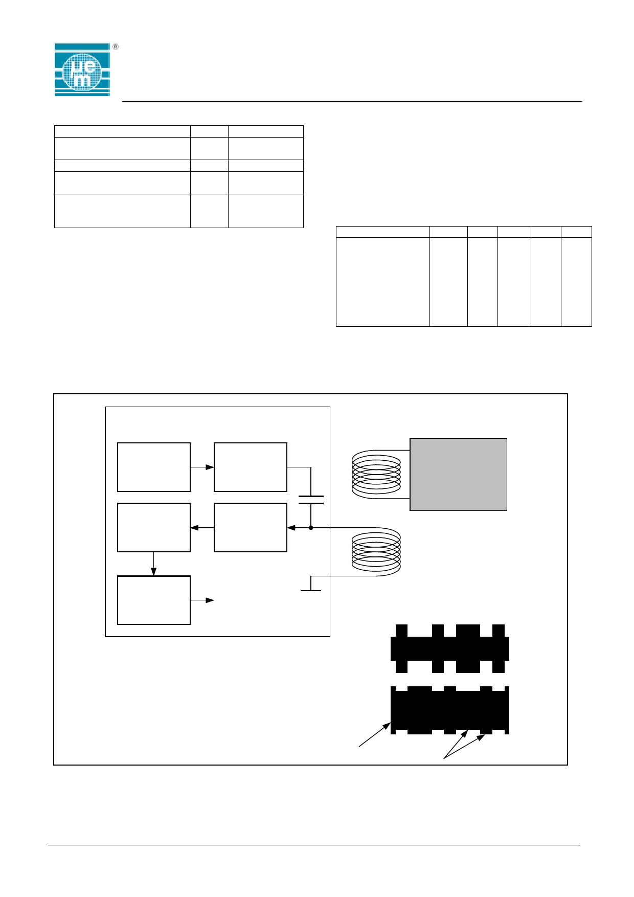
System Principle
Oscillator
Tranceiver
Antenna
Driver
Filter
and
Gain
Demodulator
EM4006
Handling Procedures
This device has built-in protection against high static
voltages or electric fields; however, anti-static
precautions must be taken as for any other CMOS
component. Unless otherwise specified, proper operation
can only occur when all terminal voltages are kept within
the voltage range. Unused inputs must always be tied to
a defined logic voltage level.
Operating Conditions
Parameter
Operating Temp.
Symb Min Typ Max Units
Top -40
+85 °C
Maximum Coil
Current
Icoil -10
10 mA
AC Voltage on Coil
Supply Frequency
Vcoil
fcoil
3 14*
Vpp
10 13.56 15 MHz
*) The AC Voltage on Coil is limited by the on chip
voltage limitation circuitry. This is according to the
parameter Icoil.
Transponder
Coil1
EM4006
Coil2
Data decoder
Data received
from transponder
Transponder coil
Signal on coils
Transeiver coil
RF Carrier
Data
Fig. 3
Copyright 2001, EM Microelectronic-Marin SA
2
www.emmicroelectronic.com
Share Link: