A117EHI 데이터 시트보기 (PDF) - MicroPower Direct, LLC
부품명
상세내역
일치하는 목록
A117EHI Datasheet PDF : 2 Pages
| |||
Model Selection Guide
Model
Number
Input
Voltage (VDC)
Current (mA)
Nominal Range Full-Load No-Load
Voltage
(VDC)
Output
Current
(mA, Max)
Current
(mA, Min)
A101EHI
A102EHI
A103EHI
A104EHI
A105EHI
A106EHI
A107EHI
A108EHI
A111EHI
A112EHI
A113EHI
A114EHI
A115EHI
A116EHI
A117EHI
A118EHI
5
4.5 - 5.5
277
5
4.5 - 5.5
256
5
4.5 - 5.5
247
5
4.5 - 5.5
250
5
4.5 - 5.5
277
5
4.5 - 5.5
267
5
4.5 - 5.5
256
5
4.5 - 5.5
256
12 10.8 - 13.2 111
12 10.8 - 13.2 104
12 10.8 - 13.2 103
12 10.8 - 13.2 105
12 10.8 - 13.2 114
12 10.8 - 13.2 111
12 10.8 - 13.2 105
12 10.8 - 13.2 105
60
5.0
60
9.0
60
12.0
60
15.0
60
±5.0
60
±9.0
60
±12.0
60
±15.0
40
5.0
40
9.0
40
12.0
40
15.0
40
±5.0
40
±9.0
40
±12.0
40
±15.0
200
111
84
67
±100
±56
±42
±33
200
111
84
67
±100
±56
±42
±33
20.0
12.0
9.0
7.0
±10.0
±6.0
±5.0
±4.0
20.0
12.0
9.0
7.0
±10.0
±6.0
±5.0
±4.0
Efficiency
(%, Typ)
72
78
81
80
72
75
78
78
75
80
81
79
73
75
79
79
Fuse Rating
Slow-Blow
(mA)
1,000
1,000
1,000
1,000
1,000
1,000
1,000
1,000
250
250
250
250
250
250
250
250
Notes:
1. Output load regulation is specified for a load change of 10%
to 100%.
2. These units should not be operated with a load under 10%
of full load. Operation at no-load may cause damage to the
unit.
3. These converters will operate without external components.
However, when measuring output ripple, it is recommended
that an external ceramic capacitor be placed from the
+Vout pin to the -Vout pin for single output units and from
each output to
common for dual
output units. An
Vin
Input
Capacitor
Vout
Output
Capacitor
input capacitor 5 VDC
will enhance sta-
bility over tem-
12 VDC
4.7 μF
2.2 μF
perature and input line variations.
5 VDC
9 VDC
12 VDC
4.7 μF
2.2 μF
1.0 μF
Recommended capacitor values are 15 VDC 0.47 μF
given in the table above. For applica-
tions requiring very low output noise levels, a simple LC filter
should be effective.
4. Dual output units may be connected to provide a 10V, 18V,
24V or 30 VDC output. To do this, connect the load across
the positive (+Vout) and negative (-Vout) outputs and float
the output common
5. It is recommended that a fuse be used on the input of a
power supply for protection. See the Model Selection table
above for the correct rating.
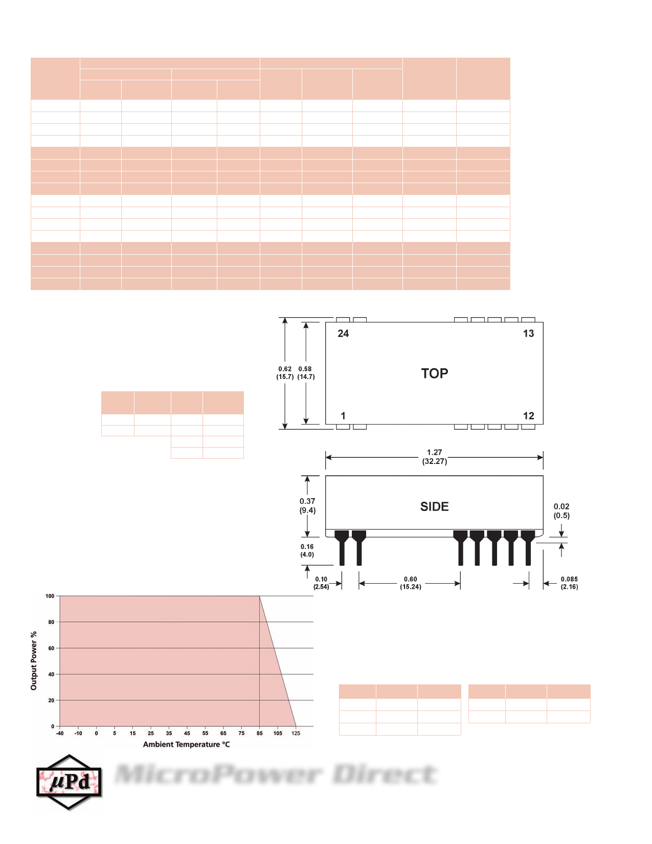
Mechanical Dimensions
Derating Curve
Mechanical Notes:
• All dimensions are typical in inches (mm)
• Tolerance x.xx = ±0.01 (±0.25)
• All pins are on a 0.1 (2.54) pitch
• All pins diameters are 0.02 (0.5)
Pin Connections
Pin Single Dual
1
+Vin
+Vin
2
-Vin
-Vin
8, 17
NC
-Vout
Pin
10, 15
12, 13
Single
-Vout
+Vout
Dual
Common
+Vout
MicroPower Direct
www.micropowerdirect.com
292 Page Street Ste D Stoughton, MA 02072 • TEL: (781) 344-8226 • FAX: (781) 344-8481 • E-Mail: sales@micropowerdirect.com
Share Link: 