NCP5666 데이터 시트보기 (PDF) - Unspecified
부품명
상세내역
일치하는 목록
NCP5666 Datasheet PDF : 9 Pages
| |||
NCP5666
APPLICATION INFORMATION
The NCP5666 is a high performance low dropout 3.0 A
linear regulator with Enable suitable for high power
applications. It is thermally robust and includes the safety
features necessary during a fault condition, which provide
for an attractive high current LDO solution for server, ASIC
power supplies, networking equipment applications, and
many others.
Input Capacitor
An input bypass capacitor is recommended to improve
transient response or if the regulator is located more than a
few inches from the power source. This will reduce the
circuit's sensitivity to the input line impedance at high
frequencies and significantly enhance the output transient
response. Different types and different sizes of input
capacitors can be chosen dependent on the quality of power
supply. The range of 4.7 mF to 220 mF should cover most of
the applications. The higher the capacitance, the lower
change of input voltage due to line and load transients. The
bypass capacitor should be mounted with shortest possible
lead or track length directly across the regulator's input
terminals.
Output Capacitor
The output capacitor is required for stability. The
NCP5666 remains stable with ceramic, tantalum, and
aluminum electrolytic capacitors with a minimum value of
2.2 mF. See Figure 12 for stable region of ESR for various
output capacitors. The range of 2.2 mF to 220 mF should
cover most of the applications. The higher the capacitance,
the better load transient response. When a high value
capacitor is used, a low value capacitor is also recommended
to be put in parallel. The output capacitors should be placed
as close as possible to the output pin of the device. This
should help ensure ultrafast transient response times.
Current Limit Operation
As the peak output current increases beyond its limitation,
the device is internally clampled to 4.5 A, thus causing the
output voltage to decrease and go out of regulation. This
allows the device never to exceed the maximum power
dissipation.
Input Voltage Operating Range
The NCP5666 is guaranteed to protect itself from self
destruction due to excessive power dissipation by activating
current limit and thermal shutdown protections. These
destructive situations can happen during very fast startup
with large output capacitors or when output is short
circuited. As long as the input voltage is lower than
maximum operating voltage (9 V), the maximum power
dissipation is never exceeded.
If input voltage is between maximum operating voltage
(9 V) and absolute maximum voltage (18 V) power
dissipation must never exceed limits specified in Thermal
Consideration section for safety operation.
To use the device over maximum operating voltage the
slow startup, not large output capacitors and no short circuit
is recommended to maintain.
Thermal Consideration
The maximum device power dissipation can be calculated by:
TJ(max) * TA
PD +
RqJA
The bipolar process employed for this IC is fully
characterized and rated for reliable 18 V operation. To avoid
damaging the part or degrading it's reliability, power
dissipation transients should be limited to 30 W for D2PAK.
For open-circuit to short-circuit transient,
PDTransient = Vin(operating max) * ISC
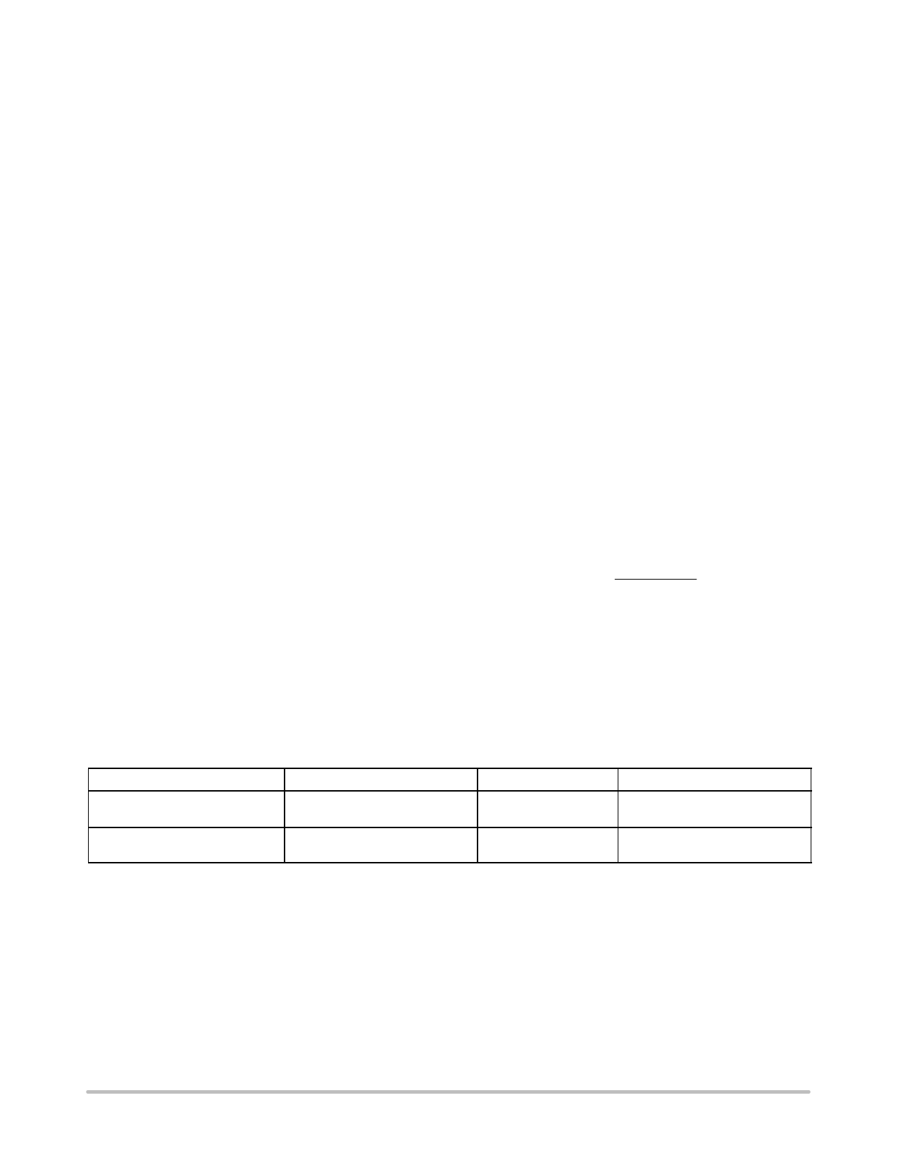
ORDERING INFORMATION
Device
Nominal Output Voltage
Package
Shipping†
NCP5666DS25R4G (Note 7)
2.5 V
D2PAK
(Pb-Free)
800 / Tape & Reel
NCP5666DS50R4G (Note 7)
5.0 V
D2PAK
(Pb-Free)
800 / Tape & Reel
7. Other fixed output voltages available at 0.9 V, 1.2 V, 1.5 V, 1.8 V, 3.0 V, 3.3 V per request.
†For information on tape and reel specifications, including part orientation and tape sizes, please refer to our Tape and Reel Packaging
Specifications Brochure, BRD8011/D.
http://onsemi.com
8
Share Link: 