VPC3211C 데이터 시트보기 (PDF) - Micronas
부품명
상세내역
일치하는 목록
VPC3211C Datasheet PDF : 48 Pages
| |||
VPC 3205C, VPC 3215C
PRELIMINARY DATA SHEET
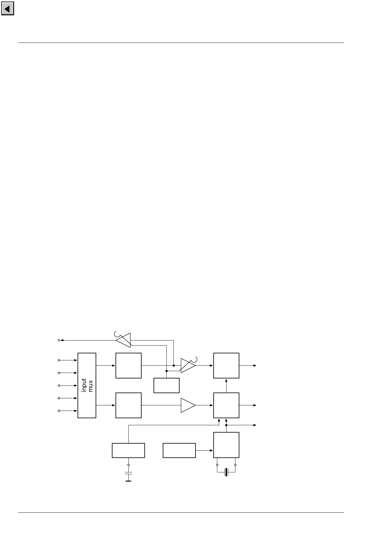
2. Functional Description
2.1. Analog Front-End
This block provides the analog interfaces to all video
inputs and mainly carries out analog-to digital conver-
sion for the following digital video processing. A block
diagram is given in Fig. 2–1.
Most of the functional blocks in the front-end are digi-
tally controlled (clamping, AGC, and clock-DCO). The
control loops are closed by the Fast Processor (‘FP’)
embedded in the decoder.
2.1.1. Input Selector
Up to five analog inputs can be connected. Four inputs
are for input of composite video or S-VHS luma signal.
These inputs are clamped to the sync back porch and are
amplified by a variable gain amplifier. One input is for
connection of S-VHS carrier-chrominance signal. This
input is internally biased and has a fixed gain amplifier.
2.1.2. Clamping
The composite video input signals are AC coupled to
the IC. The clamping voltage is stored on the coupling
capacitors and is generated by digitally controlled cur-
rent sources. The clamping level is the back porch of
the video signal. S-VHS chroma is also AC coupled.
The input pin is internally biased to the center of the
ADC input range.
2.1.3. Automatic Gain Control
A digitally working automatic gain control adjusts the
magnitude of the selected baseband by +6/–4.5 dB in
64 logarithmic steps to the optimal range of the ADC.
The gain of the video input stage including the ADC is
213 steps/V with the AGC set to 0 dB.
2.1.4. Analog-to-Digital Converters
Two ADCs are provided to digitize the input signals.
Each converter runs with 20.25 MHz and has 8 bit res-
olution. An integrated bandgap circuit generates the
required reference voltages for the converters. The
two ADCs are of a 2-stage subranging type.
2.1.5. Digitally Controlled Clock Oscillator
The clock generation is also a part of the analog front
end. The crystal oscillator is controlled digitally by the
control processor; the clock frequency can be adjusted
within ±150 ppm.
2.1.6. Analog Video Output
The input signal of the Luma ADC is available at the
analog video output pin. The signal at this pin must be
buffered by a source follower. The output voltage is
2 V, thus the signal can be used to drive a 75 Ω line.
The magnitude is adjusted with an AGC in 8 steps
together with the main AGC.
Analog Video
Output
CVBS/Y
CVBS/Y
CVBS/Y
CVBS/Y
Chroma
VIN4
VIN3
VIN2
VIN1
CIN
Fig. 2–1: Analog front-end
clamp
bias
reference
generation
AGC
+6/–4.5 dB
ADC
digital CVBS or Luma
gain
frequency
ADC
DVCO
±150
ppm
digital Chroma
system clocks
20.25 MHz
6
Micronas
Share Link: 