MC10137 데이터 시트보기 (PDF) - Motorola => Freescale
부품명
상세내역
일치하는 목록
MC10137 Datasheet PDF : 6 Pages
| |||
MC10137
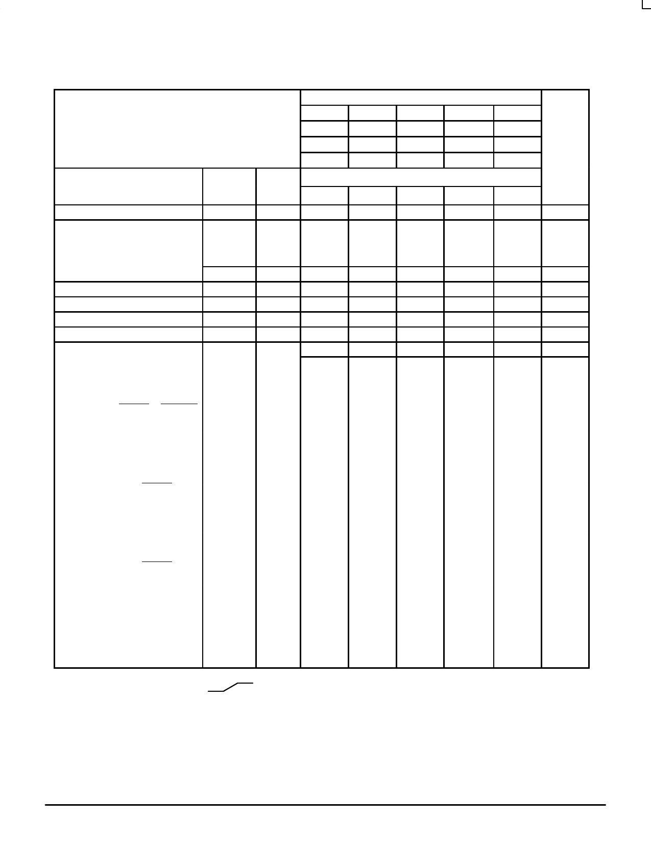
ELECTRICAL CHARACTERISTICS (continued)
TEST VOLTAGE VALUES (Volts)
@ Test Temperature VIHmax
–30°C –0.890
VILmin
–1.890
VIHAmin VILAmax
–1.205
–1.500
VEE
–5.2
+25°C –0.810
–1.850
–1.105
–1.475
–5.2
+85°C –0.700
–1.825
–1.035
–1.440
–5.2
Characteristic
Power Supply Drain Current
Input Current
Symbol
IE
IinH
Pin
Under
Test
8
5,6,11,12
7
9,10
13
TEST VOLTAGE APPLIED TO PINS LISTED BELOW
VIHmax VILmin VIHAmin VILAmax
5,6,11,12
7
9,10
13
VEE
8
8
8
8
8
IinL
All
Note 1.
Output Voltage
Output Voltage
Threshold Voltage
Threshold Voltage
Switching Times
Logic 1
Logic 0
Logic 1
Logic 0
(50Ω Load)
VOH
VOL
VOHA
VOLA
14 (2.)
14 (2.)
14 (2.)
14 (2.)
12
+1.11V
7, 9
7, 9
7, 9
7, 9
+0.31V
Propagation Delay
Clock Input t13+14+
14
12
t13+14–
14
t13+4+
4
7
t13+4–
4
7
Carry In to Carry Out t10–4–
4 (3.)
7
13
t10+4+
4
7
13
Setup Time
Data Inputs t12+13+
14
7, 9
t12–13+
14
7, 9
Select Inputs t9+13+
14
t7+13+
14
Carry In Inputs t10–13+
14
7
9
t13+10+
14
7
9
Hold Time
Data Inputs t13+12+
14
7, 9
t13+12–
14
7, 9
Select Inputs t13+9+
14
t13+7+
14
Carry In Inputs t13+10–
14
7
9
t10+13+
14
7
9
Counting Frequency
fcountup
14
7
fcountdown
14
9
Rise Time
(20 to 80%)
t4+
4
7
t14+
14
7
Fall Time
(20 to 80%)
t4–
4
7
t14–
14
7
1. Individually test each input; apply VILmin to pin under test.
2. Measure output after clock pulse VIL
VIH appears at clock input (Pin 13).
3. Before test set all Q outputs to a logic high.
12
Pulse In
13
13
13
13
10
10
12, 13
12, 13
9, 13
7, 13
10, 13
10, 13
12, 13
12, 13
9, 13
7, 13
10, 13
10, 13
13
13
13
13
13
13
12
Pulse Out
14
14
4
4
4
4
14
14
14
14
14
14
14
14
14
14
14
14
14
14
4
14
4
14
8
8
8
8
8
–3.2 V
8
8
8
8
8
8
8
8
8
8
8
8
8
8
8
8
8
8
8
8
8
8
8
8
(VCC)
Gnd
1, 16
1, 16
1, 16
1, 16
1, 16
1, 16
1, 16
1, 16
1, 16
1, 16
+2.0 V
1, 16
1, 16
1, 16
1, 16
1, 16
1, 16
1, 16
1, 16
1, 16
1, 16
1, 16
1, 16
1, 16
1, 16
1, 16
1, 16
1, 16
1, 16
1, 16
1, 16
1, 16
1, 16
1, 16
1, 16
Each MECL 10,000 series circuit has been designed to meet the dc specifications shown in the test table, after thermal equilibrium has been
established. The circuit is in a test socket or mounted on a printed circuit board and transverse air flow greater than 500 linear fpm is maintained.
Outputs are terminated through a 50-ohm resistor to –2.0 volts. Test procedures are shown for only one gate. The other gates are tested in the
same manner.
MOTOROLA
3–38
MECL Data
DL122 — Rev 6
Share Link: 