TDA2593 데이터 시트보기 (PDF) - STMicroelectronics
부품명
상세내역
일치하는 목록
TDA2593 Datasheet PDF : 6 Pages
| |||
TDA2593
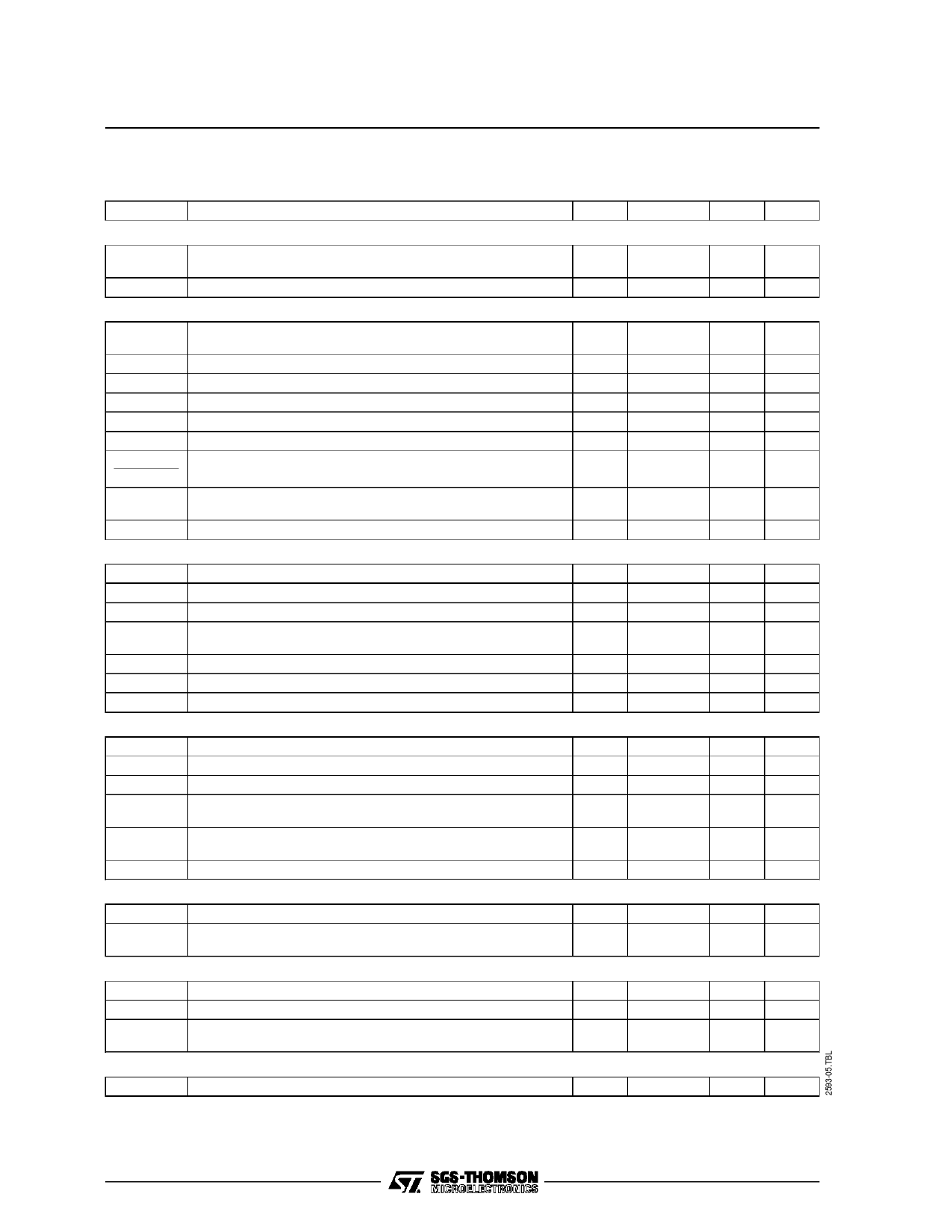
ELECTRICAL OPERATING CHARACTERISTICS (contined)
(Tamb = 25oC, V1–V16 = 12V , unless otherwise specified)
Symbol
Parameter
Min.
Typ.
Max. Unit
OVERALL PHASE RELATION SHIP
tz
Phrase Between Middle Synchro Pulse and Middle Fly-back
1.9
Pulse (tr = 12 µs, note 4
3.3
µs
∆I/∆t
Sensitivity to Current Adjust
30
µA/µs
OSCILLATOR (PINS 14 AND 15)
V14–16
I14
f
∆f
∆f/15
∆f
∆f/f
∆V/V nom.
∆f
T
Threshold Voltage (low level)
(high level)
Current Generator
Free Running Frequency (Cosc = 4700pF, Rosc = 12kΩ)
Tolerance on Frequency (note 5)
Frequence Control Sensitivity
Spread of Frequency
nfluence of Supply Voltage on Frequency (note 5)
Frequency change when decreasing the supply down to 5 V
(V1–16 = 5V, note 5)
Frequency Temperature Coefficient (note 5)
4.4
7.6
± 0.47
15625
31
± 10
±5
± 0.05
V
V
mA
Hz
%
Hz/µA
%
%
± 10
%
± 10– 4 Hz/°C
PHASE COMPARATOR ø 1 (PIN 13)
V13–16
I13
I13
R13
∆f
∆f/f
Control Voltage Range
Control Current (peak value)
Off-state Current (V13–16 = 4 to 8 V)
Output Impedance (V13–16 = 4 to 8 V, note 6)
(V13–16 < 3.8 V cr > 8.2 V, note 7)
Control Sensibility
Catching and Holding Range
Catching and Holding Range Tolerance (note 5)
3.8 to 8.2
V
±1.9 to ±2.3
mA
–1
µA
High
Low
2
kHz/µs
± 780
Hz
± 10
%
PHASE COMPARATOR φ 2 AND PHASE-SHIFT (PIN 5)
V5–16
I5
I5
R5
td
∆t/∆td
Control Voltage Range
Control Current (peak value)
Off-state Output Current (V5–16 = 5.4 to 7.6 V)
Output Impedance (V5–16 = 5.4 to 7.6 V, note 6)
(V5–16 < 5.4 V or > 7.6 V)
Max. delay Between Output Pulse Leading Edge
and Fly-back Pulse Trailing Edge (tr = 12 µs)
Static Control Error
5.4 to 7.6
V
±1
mA
–5
µA
High
8
kΩ
15
µs
0.2
%
COÏNCIDENCE DETECTOR (PIN 11)
V11–16
I11
Output Voltage
Output Current
(without coïncidence)
(with coïncidence)
0.5 to 6
V
0.1
mA
– 0.5
mA
TIME CONSTANT SWITCH (PIN 12)
V12–16 Output Voltage
I12
Output Current
R12
Output Impedance (V11–16 = 2.5 to 7 V)
(V11–16 < 1.5 or > 9 V)
PULSE GENERATOR (INTERNAL)
6
V
±1
mA
100
Ω
60
kΩ
t
Pulse Width
7.5
µs
Notes : 4. The adjustement of overall phase relation (and output pulse leading edge position) is automatically performed by phase
comparator Ø 2. If additional adjustement is needed, a current have to be imposed at pin 5.
5. Tolerance of peripheral components not included.
6. Current generator.
7. Emitter-follower
4/6
Share Link: 