PI74SSTV16859 데이터 시트보기 (PDF) - Pericom Semiconductor
부품명
상세내역
일치하는 목록
PI74SSTV16859 Datasheet PDF : 8 Pages
| |||
PI74SSTV16859
1122334455667788990011223344556677889900112233445566778899001122112233445566778899001122334455667788990011223344556677889900112211223344556677889900112233445566778899001122334455667788990011221122334455667788990011223344556677889900112233445566778899001122112233445566778899001122
13-Bit to 26-Bit Registered Buffer
Product Features
• PI74 SSTV16859 is designed for low-voltage operation,
VDD = VDDQ = 2.3V to 2.7V
• Supports SSTL_2 Class II specifications on outputs
• All Inputs are SSTL_2 Compatible, except RESET
which is LVCMOS.
• Designed for DDR Memory
• Flow-Through Architecture
• Packages (Lead-free packages are available):
– 64-pin, 240-mil wide plastic TSSOP (A)
– 56-contact, Plastic Very Thin Fine Pitch Quad Flat No
Lead QFN (ZB)
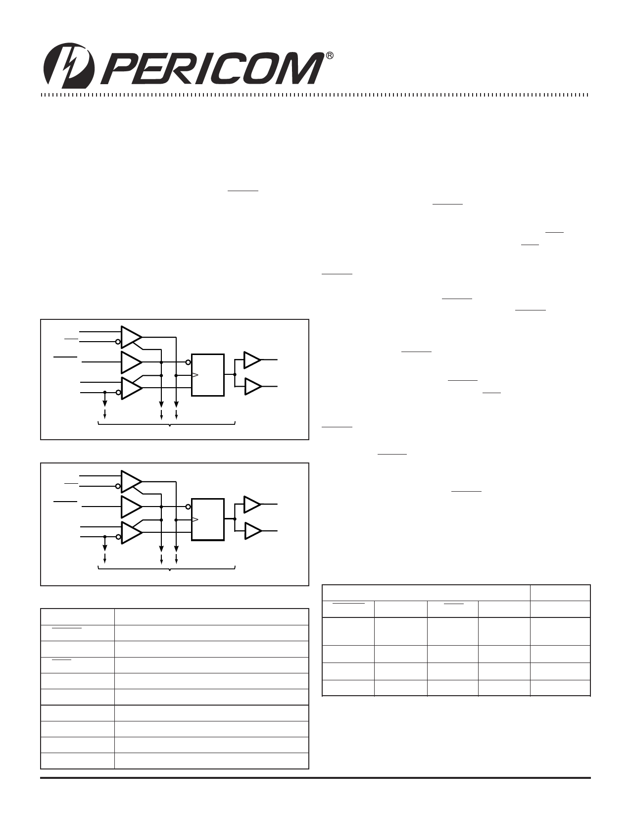
Logic Block Diagram - TSSOP
48
CLK
49
CLK
RESET 51
35
D1
45
VREF
R
CLK
D
16 Q1A
32 Q1B
TO 12 OTHER CHANNELS
Logic Block Diagram - QFN
35
CLK
36
CLK
RESET 38
24
D1
32
VREF
R
CLK
D
7 Q1A
22 Q1B
Product Description
Pericom Semiconductor’s PI74SSTV16859 logic circuit is produced
using the Company’s advanced 0.35 micron CMOS technology,
achieving industry leading speed.
All inputs are compatible with the JEDEC standard for SSTL_2,
except the LVCMOS reset (RESET) input. All outputs are SSTL_2,
Class II compatible.
The device operates from a differential clock (CLK and CLK). Data
registered at the crossing of CLK going HIGH, and CLK going LOW.
The PI74SSTV16859 supports low-power standby operation. When
RESET is LOW, the differential input receivers are disabled, and
undriven (floating) data, clock and reference voltage (VREF) inputs
are allowed. In addition, when RESET is LOW, all registers are reset,
and all outputs are forced LOW. The LVCMOS RESET input must
always be held at a valid logic HIGH or LOW level.
To ensure defined outputs from the register before a stable clock
has been supplied, RESET must be held in the LOW state during
power up.
In the DDR DIMM application, RESET is specified to be completely
asynchronous with respect to CLK and CLK. Therefore, no timing
relationship can be guaranteed between the two. When entering
RESET, the register will be cleared and the outputs will be driven
LOW quickly, relative to the time to disable the differential input
receivers, thus ensuring no glitches on the output. However, when
coming out of RESET, the register will become active quickly, relative
to the time to enable the differential input receivers. When the data
inputs are LOW, and the clock is stable, during the time from the
LOW-to-HIGH transition of RESET until the input receivers
are fully enabled, the design must ensure that the outputs will
remain LOW.
Pericom’s PI74SSTV16859 is characterized for operation from
0°C to 70°C.
TO 12 OTHER CHANNELS
Product Pin Description
Pin Name
Description
RESET
CLK
CLK
D
Q
GND
VDD
VDDQ
VREF
Reset (Active Low) LVCMOS
Clock Input, Positive Differential Input
Clock Input, Negative Differential Input
Data Input, D1-D13
Data Output, Q1-Q13
Ground
Core Supply Voltage, 2.5V Nominal
Output Supply Voltage, 2.5V Nominal
Input Reference Voltage, 1.25V Nominal
Truth Table(1)
Inputs
Outputs
RESET CLK
CLK
D
Q
L
X or
Floating
X or
Floating
X or
Floating
L
H
↑
↓
H
H
Η
↑
↓
L
H
L or H L or H
X
L
Qo(2)
Notes:
1. H = High Signal Level
2. Output level before the
L = Low Signal Level
indicated steady state
↑ = Transition LOW-to-HIGH
input conditions were
↓ = Transition HIGH-to-LOW
established.
X = Irrelevant or floating
1
PS8508D 05/01/03
Share Link: 