AVPRO-5001 데이터 시트보기 (PDF) - TDK Corporation
부품명
상세내역
일치하는 목록
AVPRO-5001 Datasheet PDF : 8 Pages
| |||
AVPro® 5001
Quad A/V Drivers
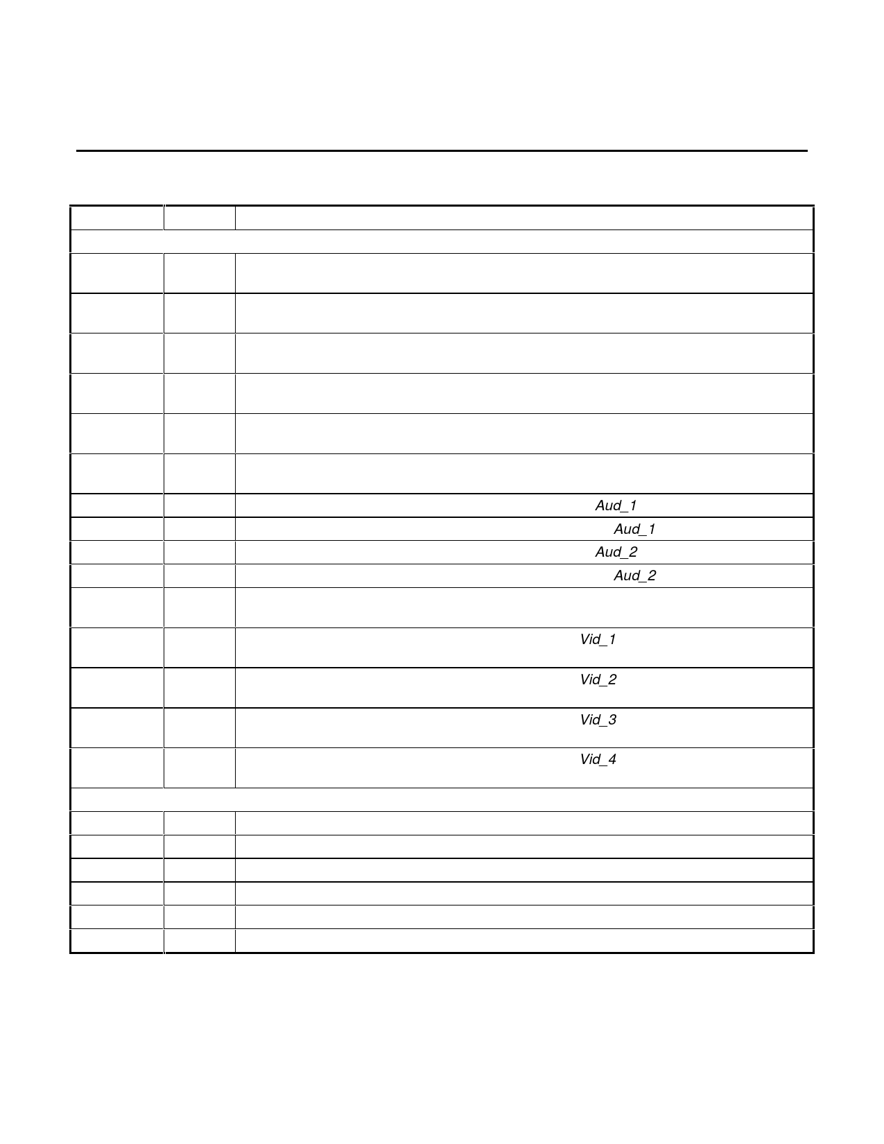
PIN DESCRIPTIONS (Pins marked N/C should be left unconnected during normal use)
NAME
TYPE DESCRIPTION
I/O Pins:
Aud_1
I
Audio input 1: This pin accepts an audio signal that can be either direct coupled or AC-
coupled. This pin is typically connected to one channel of a stereo audio source.
Aud_2
I
Audio input 2: This pin accepts an audio signal that can be either direct coupled or AC-
coupled. This pin is typically connected to the other channel of a stereo audio source.
Vid_1
I
Video input 1: This pin accepts an AC-coupled video signal. In a typical system, this pin
will be connected to a composite (CVBS) signal source.
Vid_2
I
Video input 2: This pin accepts an AC-coupled video signal. In a typical system, this pin
will be connected to a composite (CVBS) source or a green signal source (RGB).
Vid_3
I
Video input 3: This pin accepts an AC-coupled video signal. In a typical system, this pin
will be connected to a luma signal source or a blue signal source (RGB).
Vid_4
I
Video input 4: This pin accepts an AC-coupled video signal. In a typical system, this pin
will be connected to a chroma signal source or a red signal source (RGB).
Aud1_out1
O
Audio 1 output 1: This pin is the primary output for the Aud_1 input channel.
Aud1_out2
O
Audio 1 output 2: This pin is the secondary output for the Aud_1 input channel.
Aud2_out1
O
Audio 2 output 1: This pin is the primary output for the Aud_2 input channel.
Aud2_out2
O
Audio 2 output 2: This pin is the secondary output for the Aud_2 input channel.
Mode
I
Mode select: This pin selects the video mode. When left open, the device is in the RGB
mode. When connected to ground, the device is in the CVBS/S-video mode.
Vid1_out
O
Video 1 output: This pin is the buffered output of the Vid_1 input pin with a gain of 2. For
a typical 75 ohm load, an external 62 ohms should be added in series with the load.
Vid2_out
O
Video 2 output: This pin is the buffered output of the Vid_2 input pin with a gain of 2. For
a typical 75 ohm load, an external 62 ohms should be added in series with the load.
Vid3_out
O
Video 3 output: This pin is the buffered output of the Vid_3 input pin with a gain of 2. For
a typical 75 ohm load, an external 62 ohms should be added in series with the load.
Vid4_out
O
Video 4 output: This pin is the buffered output of the Vid_4 input pin with a gain of 2. For
a typical 75 ohm load, an external 62 ohms should be added in series with the load.
Power/Ground Pins:
VCCa,v
-
+5 VDC power inputs. VCCa is the audio supply, VCCv is the video supply.
VEEa,v
-
-5 VDC power inputs. VEEa is the audio supply, VEEv is the video supply.
Cbyp
-
Internal current reference bypass pin. Add capacitor 0.01 uF to ground.
GNDa,v
-
Ground for all blocks. GNDa is the audio supply, GNDv is the video supply.
RRef
-
Bias point of internal current generator. Add resistor 10.0k to ground.
Tgen
-
Reference point for internal timing circuit. Add capacitor 470 pF to ground.
3
Share Link: 