MM1454 데이터 시트보기 (PDF) - Mitsumi
부품명
상세내역
일치하는 목록
MM1454 Datasheet PDF : 5 Pages
| |||
MITSUMI
Q Surround Processor MM1454
* Note 1: 1 Input voltage amplitude when output total higher harmonic distortion is 1%. However, the signals
input to SG1 and SG2 must be the same phase (phase difference 0 degrees).
* Note 2: 2 Input voltage amplitude when f = 1kHz and output total higher harmonic distortion is 1%. However,
the signals input to SG1 and SG2 must be reverse phase (phase difference 180 degrees).
* Note 3: 3 Voltage when B/Q pin (Pin 3) is considered to be H (Q Surround mode).
* Note 4: 4 Voltage when B/Q pin (Pin 3) is considered to be L (by pass mode).
* Note 5: 5 Current that flows in to B/Q pin (Pin 3) when Vbyp = 5V.
* Note 6: 6 Current that flows out of B/Q pin (Pin 3) when Vbyp = 0V.
* Note 7: 7 The mute signal for turning off the power amp power supply is output to Pin 4. On this IC, it is
recommended that the pop noise generated during power supply fall be muted by turning off the
power amp connected to the final stage of MM1454 before turning off the IC power supply.
Tvoff
VCC=9V
VCC waveform (16PIN)
0V
Vdeth
DET pin waveform (4PIN)
Vdet 1
* Note 8: 8 Defined as the ratio between Pin 6 output signal and Pin 7 output signal when a signal is input to
SG1.
* Note 9: 9 Defined as the ratio between Pin 7 output signal and Pin 6 output signal when a signal is input to
SG2.
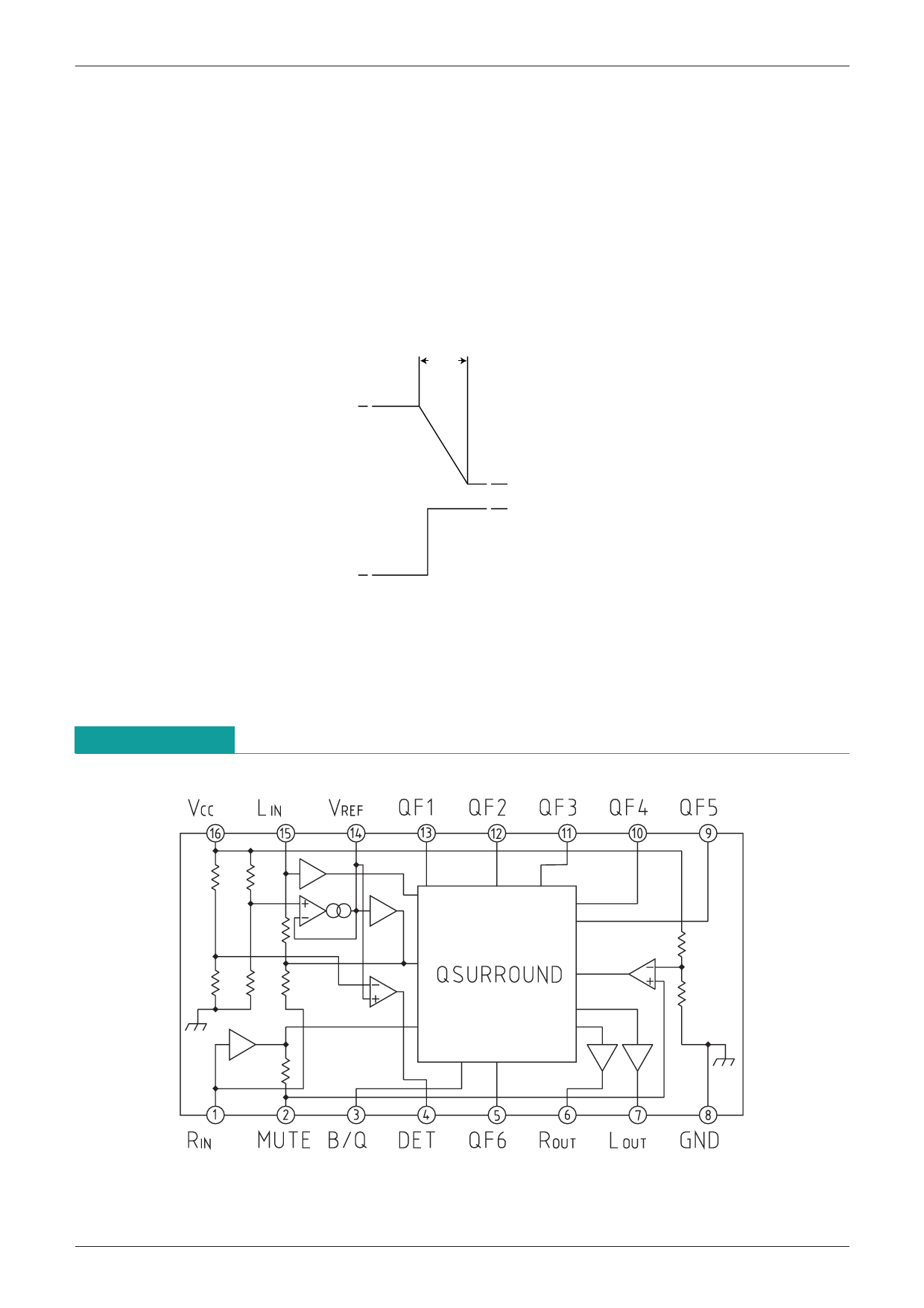
Block Diagram
Share Link: 