74HCT7540 데이터 시트보기 (PDF) - Philips Electronics
부품명
상세내역
일치하는 목록
74HCT7540 Datasheet PDF : 7 Pages
| |||
Philips Semiconductors
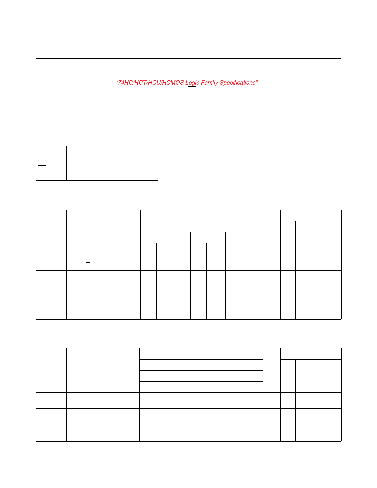
Octal Schmitt trigger buffer/line driver;
3-state; inverting
Product specification
74HC/HCT7540
DC CHARACTERISTICS FOR 74HCT
For the DC characteristics see “74HC/HCT/HCU/HCMOS Logic Family Specifications”.
Transfer characteristics are given below (not applicable for OEn inputs).
Output capability: bus driver
ICC category: MSI
Note to HCT types
The value of additional quiescent supply current (∆ICC) for a unit load of 1 is given in the family specifications.
To determine ∆ICC per input, multiply this value by the unit load coefficient shown in the table below.
INPUT UNIT LOAD
OE1
1.30
OE2
1.30
An
0.20
AC CHARACTERISTICS FOR 74HCT
GND = 0 V; tr = tf = 6 ns; CL = 50 pF
Tamb (°C)
TEST CONDITIONS
SYMBOL PARAMETER
74HCT
+25
−40 to +85
−40 to +125
UNIT
VCC
(V)
WAVEFORMS
min typ. max. min max. min. max.
tPHL/ tPLH propagation delay
An to Yn
19 32
40
tPZH/ tPZL 3-state output enable time
19 32
40
OEn to Yn
tPHZ/ tPLZ 3-state output disable time
20 32
40
OEn to Yn
tTHL/ tTLH output transition time
5 12
15
48 ns 4.5 Fig.8
48 ns 4.5 Fig.9
48 ns 4.5 Fig.9
18 ns 4.5 Fig.8
TRANSFER CHARACTERISTICS FOR 74HCT
Voltages are referred to GND (ground = 0 V)
Tamb (°C)
TEST CONDITIONS
SYMBOL PARAMETER
74HCT
+25
−40 to +85
−40 to +125
UNIT
VCC
(V)
WAVEFORMS
min typ. max. min max. min. max.
VT+
positive-going threshold
2.0
2.0
2.1
2.1
2.0 V
2.1
4.5 Figs 6 and 7
5.5
VT−
negative-going threshold 0.70
0.80
0.64
0.60
0.74
0.70
V 4.5 Figs 6 and 7
5.5
VH
hysteresis (VT+ − VT−)
0.17 0.23
0.17 0.23
V 4.5 Figs 6 and 7
5.5
December 1990
6
Share Link: 